Is it reasonable to build an amplifier for one or another and (adjustng the filament supply) simply swap between them? >>
Most definitely. This is easiest with a UX4 base. This gives you a very large choice of tubes. When I did all my initial tube testing I just used a couple of adjustable DC bench supplies, and dialled in the filament voltage. In this way I tried out the whole range of UX4 tubes. Sound is quite adequate with a good DC bench supply.
When you go over to building your proper filament supply, you can put in small pots to adjust the voltage up and down, but that's a bit trickier, and you'd need test points to check the voltage as well. Easier to do the tube rolling with an adjustable bench PSU - you have a display for the voltage and usually the current too. I have some Thurlby Thander digital ones which are nice. These are always on ebay. If you can, go for a couple of 15v at 4A. Failing that, bear in mind that a 26 is 1 amp (a common 30v 1 amp supply will work on max, since the voltage is low) and you may want to try something with higher current than that. Andy
Hi Brian,
All true of course, and in most instances the AV will be considerably less than mu and consequently the miller capacitance will be smaller too.
Notable exceptions are any triodes loaded by a ccs where AV should very closely approximate mu at least in the case where the ccs represents the ac load impedance on the tube.
The other is with transformer coupling in the case where the load impedance is a lot higher than the intended load impedance, such would be the case for any transformer coupled line stage running into a load impedance >10x the intended load impedance. My nominally 600 ohm line stage output for example is running into 70K.. In this case the primary inductance is concern at low frequencies, otherwise the plate sees a pretty high load impedance.
Doug,
Yes that was my thought too, simple reconfiguration of the filament supplies will allow you to use the 26, 01A, 12A and 30 interchangeably. I use a small 5V switcher with an additional pi filter to power the filaments in mine, and with a minor mod to add a switch could easily accomodate the 26, 01, and 12A..

Some experimentation has commenced. I picked up a pair of 01-a's and some magnequest B7 parafeed transformers. On a breadboard I loaded the plates of the tubes with a ccs at about 3.5mA, used a lm317 circuit on the filaments, and the noise and microphonics are really bad. A truck drove by on the street and the tubes picked up the vibration + the amount of background hum and noise is really high. The PS is in a separate chassis and is about 2 feet from the circuit, so I guess the place to start is with the filament supply and making the wiring neater -- it is just a bunch of clip leads right now. I also tried w/o grid stoppers, so maybe I'll add those to see if they help. I am not sure I have good feelings about this pair of tubes though.
-d
-d
Do you have a cathode bypass cap? That's one place to start - my SE stage sounded horrendous without it.
If all else fails, use differential pairs with a CCS underneath. I've had very little problems with this arrangements over a very wide array of DHTs. Even the humble 3A5 which I'm listening to right now sounds very good and is completely quiet. I put 3 O rings on it and it's fine. It's just mounted on a 4mm alu plate - no special suspended chassis or anything. Designs for CCS can be taken out of Morgan Jones book. For SE you can ground one of the grids on the input and take the output from one of the plates. Incidentally, I thought the 3A5 sounded better than two other common cathode double DHTs, the 3B7 and the 1J6.
If you're having a lot of trouble I really do recommend differential pairs of DHTs as a way of dealing with microphonics - it's not something you'd normally consider unless you have a balanced system (like me) but it works.
Eusebius said:Do you have a cathode bypass cap? That's one place to start - my SE stage sounded horrendous without it.
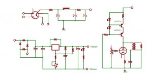
I've attached the basic schematic I am using.
There are a bunch of things that clearly can be improved -- the 6.3V winding feeds both the ez81 and the lm317 based vreg which should be changed, I probably need some work on the cathodes of the tubes, the filament PS could be better, etc. Also, this is on breadboard and is connected with lots of clip leads. But, the question is whether these things will fix things, or whether I just have a noisy pair of tubes. I built the same circuit with 6n6p's where it worked great. Obviously there is an extra layer of work with the DHTs, but I am a little weary of plunging in too deeply. Anyone have a good way to determine if a particular tube is just inherantly noisy?
Eusebius said:If you're having a lot of trouble I really do recommend differential pairs of DHTs as a way of dealing with microphonics - it's not something you'd normally consider unless you have a balanced system (like me) but it works.
The addition of grid stoppers did seem to help with microphonics a bit. One weird thing is that while there is a constant noise (60Hz, 120Hz?) there is an extra noise at about 1 second intervals that sort of sounds like a space age pinging with delay and reverb. It is very odd.
Anyhow, suggestions greatly appreciated.
Attachments
A few updates.
I swapped out the 5V linear filament supply for a switcher i had around (the one that came with my Squeezebox.) I have no idea the qualty of this PS, though I assume it is low. However, I assumed that since it is a switcher that all the noise would be HF noise and would at least be different and would show where the problems were coming from. Counter intuitively (to me anyway) the noise went way up with the switcher. I would guess that it is 120Hz noise, though I have no easy way to measure that.
The other thing that was surprising is that turning off the PS but leaving the filament supply on -- essentially letting it run from the cap bank until they discharged, all noise went away and it played pretty clear music. However, as it was about to run out of power, the noise crept back in.
I don't know what these two things mean, but I am hoping that someone else does and that they offer a clue of where to start.
Thanks,
-d
Sounds like your plate supply is noisy (lots of ripple?) or the power transformer is close enough to the tubes to cause problems. 01A are very sensitive to both magnetic and electrostatic pickup.
You should definitely add a cap to bypass the cathode bias resistor. Note that the nominal plate resistance of 8 - 9K may be triple this amount if the cathode resistor is unbypassed depending on the value of that resistor.
I usually use a pair of small resistors (22 ohms typically) in series across the filaments and connect the bias resistor and cap to the center node. I have found that this can help a lot with noise on the filament supply - it may or may not help here. (It's just about mandatory if ac is used for heating, using ac is obviously not something you should do in a dht pre-amp.)
I actually prefer fixed bias via batteries applied to the grid, I use something like a 220K grid resistor and a 9V battery - works really well.
I have also tried nicads in the cathode circuit, they are ok, note that nimhs seem to sound really lousy. (Interestingly higher internal impedance than good nicads) Normal operation will keep them charged but they do need to be replaced every few years.
kevinkr said:Sounds like your plate supply is noisy (lots of ripple?) or the power transformer is close enough to the tubes to cause problems. 01A are very sensitive to both magnetic and electrostatic pickup.
This is what is weird. the PS is about 2 feet away in a separate chassis, and the supply is reasonably clean, and the CCS should clean it further.
Eusebius said:Have you tried the cathode bypass cap yet?
kevinkr said:You should definitely add a cap to bypass the cathode bias resistor. Note that the nominal plate resistance of 8 - 9K may be triple this amount if the cathode resistor is unbypassed depending on the value of that resistor.
I'll try that tonight. I was really hoping to keep the electrolytics out of this thing, but I'll see. I'll also try adding a pair of 20R resistors on the cathodes. Would the higher plate resistance lead to more noise here?
I actually prefer fixed bias via batteries applied to the grid, I use something like a 220K grid resistor and a 9V battery - works really well.
kevinkr said:I have also tried nicads in the cathode circuit, they are ok, note that nimhs seem to sound really lousy. (Interestingly higher internal impedance than good nicads) Normal operation will keep them charged but they do need to be replaced every few years.
If all else fails, I'll give this a shot too.
Eusebius said:I was really hoping to keep the electrolytics out of this thing>>
Sure - I use 47uF polypropylenes for cathode bypass.
good idea
pair of 71a amps in here-
http://www2u.biglobe.ne.jp/~tossie/contents-E.010106.html
- Status
- This old topic is closed. If you want to reopen this topic, contact a moderator using the "Report Post" button.
- Home
- Amplifiers
- Tubes / Valves
- 71a Line Stage and Miller Capacitance