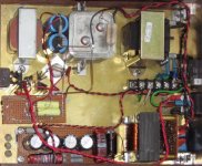
pre amp guts
Thank you SY, I really appreciate that. It was fun. I threw everything but the kitchen sink into it, as I am impatient and wanted to try as many new (to me) concepts as possible (for sure gonna try led bias too).
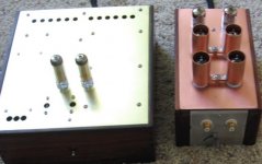
Here's the preamp guts. Took me awhile to figure out how to get the image properly sized.
Thank you SY, I really appreciate that. It was fun. I threw everything but the kitchen sink into it, as I am impatient and wanted to try as many new (to me) concepts as possible (for sure gonna try led bias too).
Here's the preamp guts. Took me awhile to figure out how to get the image properly sized.
Attachments
Brian Beck said:Sheldon,
Very nice work indeed! Can we all come over for a listen?
Anytime you are in this corner of the country (San Diego area).
Sheldon
SY said:Which tube sockets did you use?
The first two tubes each side are sitting in those spiffy teflon jobs from DIY Hi Fi Supply. Pricey, but very well made. The cathode followers are using some regular ceramic sockets I had on hand. BTW, I'm actually using 7308's for the followers. I guess that a variety of tubes could be used in that position without much change in performance.
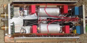
Another little note: The top of the preamp section is a plate of copper sandwiched with a plate of aluminum. It's pretty nicely damped without anything between the two.
Sheldon
lec bias
I disconnected the 2.8k cathode resistor and replace it with a green low current diode. Also shown here is a 200k resistor to B+, in order to feed the led a little more current. I haven't connected that up yes, just running with the led.
I left the cathode bypass cap in place, figuring that they would neither add nor take away much, as the led will shunt at least 99% of the AC to ground.
I sorta checked the dynamic impedance of the diode by testing with 0.5mA and 1.0mA current. The respective voltages were 1.80 and 1.82.
Sounds fine. Haven't listened enough to tell a great difference, but no worries with overload, that's for sure.
Sheldon
Attachments
I did a little crude testing of the preamp section too. Removed (per SY's suggestion in another thread) the caps bypassing the LED. No increase in noise detectable, and if there is a difference in sound, it's a very subtle one, so I left them out.
As the power supply is very quiet, I tried disconnecting the noise canceling bits. No measured or audible increase in residual noise. So the circuit could be simplified as follows, if used with a quiet supply (as below).
I went ahead and left the Broskie Aikido inspired elements in, as they added no noise and may also cancel any load induced noise at the plates.
Attachments
I love sheldon's schematic. Very innovative and I bet it sounds great. I went a little different direction but am very pleased with my results also. My input stage is similar to his output. ECC85, two halfs in parallel for low noise with resister loading for increased gain versus totem pole style. 6DJ8 cathode follower to easily drive low resistance RIAA and Russian teflon caps (Play with the RIAA calculator on the KAB site.) I tried 6N1P and 6DJ8 input. ECC85 has more gain, lower noise, less tendancy to oscillate and sounds good. The back end is the standard Aikido w/6SL7 input for high gain. I used 6SN7 for the final cathode follower. Very low noise. Will drive most any power amp direct. I like it. By the way, do not skimp on the power supply just because it is Aikido. Big improvement when I upgraded from a good quality heavy duty standard power supply.
Sheldon I really like your innovative approach and I want build it, the only thing I don't want use the input transformer, really out of budget for me, can you suggest some other way to get a good result without transformer, my pickup is a 47k Audio Technica....all the best...Acky
Typical Moving Magnet (or Moving Iron) cartridges will have high enough output so that the step-up transformer is not needed. Some high-output MC cartridges may also work OK. I can't tell from your description what kind of cartridge you have, but if the 47k refers to the input load, it would be typical for a MM or MI cartridge.
Sheldon
Sheldon
my cartridge is the Audio-Technica AT95E...
That has a standard output level, 3.5mV @ 5cm/sec. No step-up needed.
I did a little crude testing of the preamp section too. Removed (per SY's suggestion in another thread) the caps bypassing the LED. No increase in noise detectable, and if there is a difference in sound, it's a very subtle one, so I left them out.
As the power supply is very quiet, I tried disconnecting the noise canceling bits. No measured or audible increase in residual noise. So the circuit could be simplified as follows, if used with a quiet supply (as below).
I went ahead and left the Broskie Aikido inspired elements in, as they added no noise and may also cancel any load induced noise at the plates.
ecc 88=>oscilator galore.
next question.., what the hell is r3, r22,r23 ???
running framegrids at such small currents, i just wonder the negative effects, noise.
literally 3x ecc88 should be replaced by low capacitance fets.
- Status
- This old topic is closed. If you want to reopen this topic, contact a moderator using the "Report Post" button.
- Home
- Amplifiers
- Tubes / Valves
- RIAA Phono Amp Design