When I started making TubelabSE amplifiers I realized that testing newly built PC boards was a pain. I would drag out a set of transformers, tack solder the wires to the PC board, then test everything, only to disconnect the transformers and put them away. People assembling amplifiers also told me that they would like a better way to hook up the transformers. I decided to use connectors on my latest design. That worked out well so far.
I am always trying experiments with different transformers, tubes, chokes and so forth. The connectors made it easier to do this. I have ordered a batch of PC boards for this amp and I would like to have a way to test a newly built board without the setup time. I started thinking............
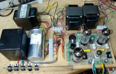
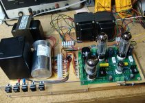
Then I thought of a way that I could test a board, or an OPT, or a power transformer, or choke, with only a screwdriver. So, I built it!
It is ugly, so call it a breadboard, or a test fixture. The pins that are used to plug into the screw terminals on the PC board were saved (for a long time) from my earlier life making SS-50 buss computers. The "euro - style" terminal strips are from All Electronics (also available at Radio Shack). Each OPT and the power transformer are connected using one of these.
It is not even finished yet, and I have already cranked through about 5 different sets of OPT's and 3 power transformers. I have several more waiting to be tested. After playing with it this weekend, I added the switch panel. It is not all connected up yet, but I will be able to switch from UL to triode, turn on or off the cathode feedback, switch from tube to SS rectifier, and go into standby.
I am always trying experiments with different transformers, tubes, chokes and so forth. The connectors made it easier to do this. I have ordered a batch of PC boards for this amp and I would like to have a way to test a newly built board without the setup time. I started thinking............
Then I thought of a way that I could test a board, or an OPT, or a power transformer, or choke, with only a screwdriver. So, I built it!
It is ugly, so call it a breadboard, or a test fixture. The pins that are used to plug into the screw terminals on the PC board were saved (for a long time) from my earlier life making SS-50 buss computers. The "euro - style" terminal strips are from All Electronics (also available at Radio Shack). Each OPT and the power transformer are connected using one of these.
It is not even finished yet, and I have already cranked through about 5 different sets of OPT's and 3 power transformers. I have several more waiting to be tested. After playing with it this weekend, I added the switch panel. It is not all connected up yet, but I will be able to switch from UL to triode, turn on or off the cathode feedback, switch from tube to SS rectifier, and go into standby.
Attachments
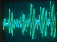
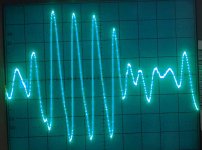
While playing with this amp, and testing the different output transformers, I captured this bass guitar run on my storage scope. This is a burst of 5 notes, each at about 90 HZ. The scope is set at 5 volts per division and connected directly across the left channel speaker. There are clean waves of about 35 volts peak to peak, across an 8 ohm (nominal) speaker. This is from an EL-34 in triode mode. Cathode feedback is on.
Attachments
Same trace, zoomed in to 10 mS per division.
I will have more pictures and test data in the next few days (time permitting) I plan to test several different OPT's and plot frequency response on them.
I am planning to order a pair of new OPT's that support UL mode. The only ones that I currently have are the small Edcors. I was planning to get a pair of the larger Edcors, but I may go with a pair of Hammond 1628SE's just because of the multiple secondary taps. This would allow me to test different tubes under different loads.
OH, the test sgnal is a CD. Gypsy Soul, new Flamenco. It is a Narada sampler CD of various "new styles of Flamenco guitar" The track used is #11. It contains a bass guitar solo that will find the limits of your amp. Later in the same track the bass is played over the Spanish guitar. Can you say intermodulation test!
Attachments
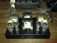
Let me show you what ugly means...
That is not even close to ugly! I have seen (and built) far worse. If we need to have an ugly amp contest, I need to make a trip to the warehouse to visit the "amps that didn't make it corner". Everyone has built one (or more) of those amps that we don't talk about on the forums. You know, the one that you hastilly put together, that never worked, or smoked on initial power up. I have a few of those, that I rob for parts now and then.
tubelab.com said:There are clean waves of about 35 volts peak to peak, across an 8 ohm (nominal) speaker. This is from an EL-34 in triode mode. Cathode feedback is on.
20W from an EL34 in triode mode single ended?

Usually that's written under. I have here one about 20mm long that is 380V rated, 17mm ones are 250VDC rated IIRC.
Also 30mm ones are 500VDC, but that can depend on the material.
And always IIRC, laws about electrical safety impone that the voltage rating should be written on the connector.
Also 30mm ones are 500VDC, but that can depend on the material.
And always IIRC, laws about electrical safety impone that the voltage rating should be written on the connector.
20W from an EL34 in triode mode single ended?
35 volts P-P across an 8 ohm resistor would be almost 20 watts. I know my speaker is NOT 8 ohms at 90 HZ, although I don't know what it really is.
I have not taken the time to accurately measure the power under the conditions that I am currently running the amp. I would suspect power near 10 watts since I am running 480 volts B+ and a 3000 ohm load. The cathode feedback allows me to lower the load impedance without sounding gross, and the high B+ gives a lot of headroom.
I am running 60 mA of tube current with 435 volts across the tube. 480 volts - 33 (cathode resistor) - 12 (OPT) = 435 volts. This gives a total tube dissipation (plate and screen) of 26 watts. Near max, but the JJ EL-34's show no signs of distress. This was not the case with the "Winged C's".
This combination sounds excellent on real music, but I haven't made measurements yet. Real measured data under different load conditions with several different transformers will follow shortly. That is one of the reasons for building this amp.
The connectors that I am using are marked 450 volts right on the terminals. It is not clear what the conditions are (AC, DC). I have the wiring arranged such that no two adjacent pins have more than 350 volts across them. I have used these connectors in my P-P breasboard with 550 volts across them. If they are going to fail, I want to find out here under controlled conditions (with a fire extinguisher nearby). I would imagine that the worst case test would be mounted to a grounded metal chassis, which is not the case in either of my breadboards.
arnoldc said:You call that ugly?You've got one of the neatest, coolest prototyping rig!
Let me show you what ugly means...
Hey, is that an El34 PP amp? I think that is going to be my next project, so could you send me the schem, and some info about it?
Tubelab,
is the september date on the SimpleSE boards still practical?
also
could you post a full-res schematic of the Simple SE?
is the september date on the SimpleSE boards still practical?
could you post a full-res schematic of the Simple SE?
The boards are due back from the fab house next week. I will build a few in the process of generating the assembly manual. Then they will be tortured to make sure that the design passes my survivability standards. If all is well they should be available in mid September.
The breadboard amp shown in this thread was designed for testing freshly built boards. It is also being used to generate a matrix of different tubes, power transformers, and output transformers. I will post the data on the web site when finished. The SimpleSE board that is in there now has survived everything that I have thrown at it for almost two months.
I posted the Eagle schematic that I used to make the PC board. I have to draw it from scratch in Visio in order to post a full resolution Jpeg. I should have it finished in a week or so.
alexmoose said:
Hey, is that an El34 PP amp? I think that is going to be my next project, so could you send me the schem, and some info about it?
Yes, it is. It's still experimental, but right now it sounds good already. I'm experimenting an OPT made by a friend who claims to use Z-cores whatever they are.
tubelab, sorry for the OT.
I reduced some of the ugliness by dropping in a shiny new circuit board. I got the batch of boards back from the board house on Monday, and had the first one built and playing music in just over 1 hour. This amp makes testing a new board easy. The board swap took about two minutes. It played flawlessly all day Tuesday.
Attachments
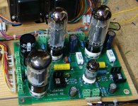
Those OPT's are One Electron UBT-3's. I have used several different OPT's in this amp since it now takes me about two minutes to change them. I have been testing different OPT - tube combinations for the construction manual for this amp. Expect a big report with real measured data in a few weeks. I ordered some more Hammond and Edcor transformers to add to the test.
I found an anomally which I just solved this weekend. While testing transformers, I discovered that a 5K ohm transformer was the best compromise for power and distortion. I also found that a 3K ohm transformer made for an SE 300B (UBT-3 and Transcendar 300B) sounded better. The lower impedance transformer had better bass, was louder, and had more punch, despite being down almost 3 watts for the same distortion level.
Then I found the impedance VS frequency curves for my speakers. My "8 ohm" speakers are over 20 ohms at 90 Hz. That explains the 35 volts peak to peak from a trioded EL-34 shown in a previous post (same transformers). The EL-34 is seeing a leisurely 7500 ohms at this frequency.
I plan to offer boards, semi - kits (no cabinet or chassis), and eventually complete kits. I should have them ready in September. I will be out of town for most of August, so I won't start until I return.
I can't set a firm price on the boards until I get a firm price quote from the vendor. Since the ROHS initiative most PC board vendors had to change their process to comply, which resulted in price increases. The vendor I have used in the past is no longer competitive for "small production runs". I got these boards from a new supplier as a "new customer special". They are better quality "made in the USA" boards. I am waiting on a firm price quote from them. I would expect them to be around $39 if the "web based cost estimator" is correct.
tubelab.com said:Another picture.
I will be out of town from Friday until next Tuesday without internet. I am taking the laptop to finish the full schematic. I should have it ready to post when I return.
Any news on the schematic? I have a 6v6gt se amp and I want to rebuild to EL34 (or the like) SET. I checked your site (very nice!!) but could not find the complete schematic.
Thanks!!
Jeroen
tubelab.com said:While playing with this amp, and testing the different output transformers, I captured this bass guitar run on my storage scope. This is a burst of 5 notes, each at about 90 HZ. The scope is set at 5 volts per division and connected directly across the left channel speaker. There are clean waves of about 35 volts peak to peak, across an 8 ohm (nominal) speaker. This is from an EL-34 in triode mode. Cathode feedback is on.
Let me guess... Are you trying a lead guitar speaker with a bass guitar?
- Status
- This old topic is closed. If you want to reopen this topic, contact a moderator using the "Report Post" button.
- Home
- Amplifiers
- Tubes / Valves
- Ugly, but versatile, new amp