Excessively many capacitors in the circuit sound signla.
C1 is not needed.
VIMA MKS capacitors is not good for sound schemes.
well FKP
6S33S requires less resistance in the grid 1, or may not be stable current anode.
I think C1 is needed because there are too many capacitors in the signal
 (and they are too big maybe). But, as it is a built and tested circuit, we can believe it works ok (maybe)
As I said, I don’t have experience with 6S33S. Just my impressions at looking the schematic.
Quality signal sources do not have DC output.I think C1 is needed because there are too many capacitors in the signal
As I said, I don’t have experience with 6S33S. Just my impressions at looking the schematic.
Potential grid 1 of the first triode tube is zero.
Capacitor is not needed.
You can easily get rid of the capacitor C2.
A large number of capacitors to cause a phase shift to low frequency. This may lead to an increased distortion, and make the auto power generator.
The scheme presented here, it's a cliché usually an engineer,
little thought it, but it should work.
Forgive me for my bad English.
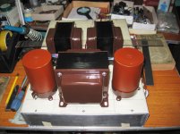
Very nice set.i am building a pp 6C33 in the coming moths...
and there are lots of schematics in the net to choose from....
Do you have the characteristics of the output transformer?
What is the Raa?
I would discourage you from using 6S33S.
Poor use of this tube in PP AB fixed offset.
I've thought about it. It would be very wasteful and hot, but would work well. I've played with the Russian 6N13S (6AS7G) and the 6336A and garter bias works very well. A good starting point is to stack two of the same cathode resistors you normally would use for a given operating point, and increase the supply voltage to suit. Easy to experiment with.
Also, if you go this route, please start a new thread, I would love to see another nice brainstorming thread, and it's nice to see the 6C33C in an application other than crappy OTL
Also, if you go this route, please start a new thread, I would love to see another nice brainstorming thread, and it's nice to see the 6C33C in an application other than crappy OTL
I was considering building a PP 6C33C amp, but I think when the time comes I'll use 6C41C which is essentially half of a 6C33C. They are far less money, and AFAIK should operate like both sections of a 6N13S in parallel. Right now I'm running 6N13S paralleled into a 600R load. 150V/80ma OP. It makes 6W sine wave drive, more with music.
- Status
- This old topic is closed. If you want to reopen this topic, contact a moderator using the "Report Post" button.
- Home
- Amplifiers
- Tubes / Valves
- A request for PP 6c33c Schematics