Hi all,
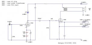
I´ll try led bias in my tube amplifier and improve ground amp schematic. I made a simplified tube amp schematic (see att. files) with 3 (chassis) ground points, one near RCAs, another near AC plug and another near power transformer.
I´d like to know if my amp ground schematic is ok?
Any comments or suggestions are very welcome.
Katapum
Attachments
If I understand you correctly this is not the best way to do your grounds.
There should be one, and only one ground connection for internal ground wiring in the chassis. Everything should be brought back to this single chassis grounding point. Now there are several acceptable ways, some are possibly better than others.
You can daisy chain or bus all of the grounds together in a specific part of the circuit, and bring back a single wire to the common ground point for each stage.
You can star ground each and every component essentially running a ground wire for every component. (I'm not a big fan of this approach as it increases loop area within the circuit and may increase emi susceptibility in some instances. Exception: PS caps.)
Some combination of both generally works well.
Stereo RCA jacks (should be isolated from chassis) can be a special case, and I have found that using a single common ground connection for both channels right back to the common (star) gnd can save a lot of grief by eliminating an internal loop between the two channels.
On the power transformer high voltage center tap and the first filter cap, it is usually better to connect the center tap to the cap negative terminal and then run from here to the central ground point. This keeps the high charging cap charging currents out of the grounding point as there is a complete loop for the charging currents through the cap without passing through the common grounding point. Usually makes little difference, but with large caps it can really help.
The external earth safety ground does not in most cases need to be connected right at the star/common grounding point, but in very low noise low level applications it might make a difference particularly with a steel chassis. (Edy currents in the steel chassis mean there may be a potential difference between the common ground and AC ground points, and depending on external paths through other grounded components can result in an aggrevated hum loop.)
Hi,
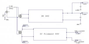
No. The amp has 3 (chassis) ground points.
It’s a Sakuma method.
http://www10.big.or.jp/~dh/index.html
Where should I connect CCS ground?
Should I connect GND2 to GND1?
Katapum
Where are you going to join them all , at GND1 and then to the power socket ?
No. The amp has 3 (chassis) ground points.
If I understand you correctly this is not the best way to do your grounds.
It’s a Sakuma method.
http://www10.big.or.jp/~dh/index.html
Where should I connect CCS ground?
Should I connect GND2 to GND1?
Katapum
Attachments
"No. The amp has 3 (chassis) ground points."
From my experience this seems like a good way to induce ground loops. I have had very good experience with seperate star grounds, each referenced to the next highest current node. (ie in your case GND3 to GND2 to GND1 to socket). Think of it as tributaries of a great river flowing to the sea. The small resistances involved encourage the current to flow to the highest current point and not to the lowest, that been your sensitive small signal grounds.
"Where should I connect CCS ground?"
When doing this myself, I took it to the small signal ground, ie GND3.
Shoog
While I greatly admire Sakuma's talent and have heard several amplifiers based on his designs, referencing different points in an amplifier circuit to different chassis grounding points seems like a really good way to build a noisy amplifier. It's just not good practice. (Before I knew better I did similar things as did lots of designers in the past.)
Note that an amplifier with a steel chassis and an EI transformer will have magnetically induced currents flowing all through the chassis. What this actually means is that no two grounding points will be at exactly the same potential, and worse that potential difference is the result of harmonic rich AC edy currents in the chassis, which then injects hum components into the audio path that needn't be there at all.
I have measured differences of a mV or more from one ground point in a steel chassis to another and this can result in audibly higher hum levels - also since the leakage flux from the transformer usually contains large amounts of 3rd harmonic this can be a lot more audible than straight hum.
In theory this might not be an issue with aluminum chassis as they are non-magnetic, but as I have not done any measurements with AL chassis I cannot be sure that it isn't a problem here too.
Just the voice of my experience here, YMMV.. (I've made lots of mistakes over the years..)
Edit to fix typo and some additional clarifications
Note that an amplifier with a steel chassis and an EI transformer will have magnetically induced currents flowing all through the chassis. What this actually means is that no two grounding points will be at exactly the same potential, and worse that potential difference is the result of harmonic rich AC edy currents in the chassis, which then injects hum components into the audio path that needn't be there at all.
I have measured differences of a mV or more from one ground point in a steel chassis to another and this can result in audibly higher hum levels - also since the leakage flux from the transformer usually contains large amounts of 3rd harmonic this can be a lot more audible than straight hum.
In theory this might not be an issue with aluminum chassis as they are non-magnetic, but as I have not done any measurements with AL chassis I cannot be sure that it isn't a problem here too.
Just the voice of my experience here, YMMV..
(I've made lots of mistakes over the years..)Edit to fix typo and some additional clarifications
Hi all,
Thanks a lot for your help.
To Kevinkr:
4 years ago I built the amp exactly with a ground schematic exactly as you wrote.
But it was an incredible noisy amplifier. Now I believe ground method isn’t the problem but filaments circuit (… maybe I´m wrong). So 2 years ago I rebuilt the entire amp with Sakuma ground method.
My little gainclone has more hum than my tube amp. My tube is VERY quite with my 94dB speakers.
It´ll be my tube amplifier number 10 versions.
Katapum
Thanks a lot for your help.
To Kevinkr:
4 years ago I built the amp exactly with a ground schematic exactly as you wrote.
You can star ground each and every component essentially running a ground wire for every component.
But it was an incredible noisy amplifier. Now I believe ground method isn’t the problem but filaments circuit (… maybe I´m wrong). So 2 years ago I rebuilt the entire amp with Sakuma ground method.
My little gainclone has more hum than my tube amp. My tube is VERY quite with my 94dB speakers.
Just the voice of my experience here, YMMV.. (I've made lots of mistakes over the years..)
It´ll be my tube amplifier number 10 versions.
Katapum
As I indicated YMMV may vary, and I was not advocating for the pure star ground as this is a good way to create large loop areas in the audio path. Still imho one ground point and a very heavy ground bus seem like better practice to me.
My speakers are about 12dB more sensitive than yours so this is a very big issue for me, and why I spent a lot of time on this subject. Engineering school and experience taught me a little more about good grounding practice as well.
Still if it is quiet enough in your system that the noise is unobtrusive to you then that ought to be more than good enough, our ears are afterall supposed to be the final arbiter..
Hi,
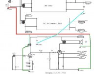
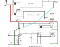
As I’m trying to improve amp ground why not to follow your advices and rebuild once more my tube amplifier.
So I made another ground schematic with one point connected to steel chassis.
Is it ok?
PS: Power transformer without centre tap.
Katapum
I´ll try led bias in my tube amplifier and improve ground amp schematic.
As I’m trying to improve amp ground why not to follow your advices and rebuild once more my tube amplifier.
So I made another ground schematic with one point connected to steel chassis.
Is it ok?
PS: Power transformer without centre tap.
Katapum
Attachments
Yes, I too have had some troubles when I deviated from the single star ground. I have found solid state to be much more forgiving than tube in this respect, but even here, it can be the difference between a good amp and a great amp. I now run all grounds (even bypass caps, shields and input connectors) separately via individual wires back to the star. I had seen this in some amp design books and it was useful.
Sorry to hijack this thread. This is off topic.
Katapum,
This thread is a little old so I doubt that you are still following it, but. . .
I read a thread a while back in which you built a transformer based spdif in/out for a dac transport. You had left a couple values blank on the schematic for the H-pad.
http://www.diyaudio.com/forums/attachment.php?s=&postid=764002&stamp=1131660111
If you are out there, could you please contact me?
- Status
- This old topic is closed. If you want to reopen this topic, contact a moderator using the "Report Post" button.
- Home
- Amplifiers
- Tubes / Valves
- CCS/5842/300B ground schematic.