The Red Light District- another pp EL84 amp
I've got a more complete write-up appearing in Bas Horneman's diy magazine, but wanted to put up some schematics for those who want to get a head start. It's easy to build, sounds great, and is a good answer for the common question, "Does anyone know a good 15W amp I can build...?"
First, the basic signal circuitry. Input stage is ECC81 (preferably JJ). Output stage is EL84 (again, JJ is a good choice).
Attachments
The power supply. B+1 is for the output stage and runs 300-350V. The regulator is for the screens (idle current adjustment) and runs from 250-300V. Adjust idle current to 85mA per EL84 pair. B+2 is for the driver stage and is 350-400V.
Attachments
Giaime said:
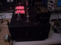
But I NEED to see where you mounted all those leds, how, and would like to see a photo of the amp in the dark
http://www.diyaudio.com/forums/showthread.php?postid=840474#post840474
And a darker shot:
Attachments
and for the more "creative & artistic" you could change a couple of the red led's for another colour and spell something out... EL 84 POWER
or whatever floats your boat. Why worry about a few milliamps one way or the other for the biasing, whats the worst that could happen?
It may stop working, distort, a runaway tube...

or whatever floats your boat. Why worry about a few milliamps one way or the other for the biasing, whats the worst that could happen?
It may stop working, distort, a runaway tube...


Even with 84 LEDs between the channels, you need five more LEDs to do the job. No great problem; use the extra five in the vertical line on the left character and power them from somewhere else...
Edit: Just realised I'd made an error - it actually needs eight extra LEDs. Perhaps the four either side of the left hand character?
Edit: Just realised I'd made an error - it actually needs eight extra LEDs. Perhaps the four either side of the left hand character?
Attachments
- Home
- Amplifiers
- Tubes / Valves
- The Red Light District - another PP EL84 amp