I am brain-challenged for PCB design, so that will have to be someone else. I think Jack Walton did a design a few years back, but it was too expensive because of the size.
The bigger version keeps getting pushed back in my queue. I wish I had more lab time...
I had the design in Ultiboard, didn't seem much interest. Lemme see what I can work up again.
ok thats cool but what voltage should i be seeing at the cathode of the final's ?
Forgot to mention i am using a 6H*6 instead of the el84 seem to be similar, i think maybe i'am wrong neebie ere .
i'am seeing about +9.38v at the cathodes 9.6v across 1 resistor on the led array , screen reg voltage 290v and plate current is 8.26mA .
P.S
ok ,i have removed the led array from the cathode , and put in place a positive voltage supply of around 7v or so on the cathode , plate went up to 44mA and screen voltage holding at to 290 , could the the led array be at fault here seems it could may i'am wrong
Forgot to mention i am using a 6H*6 instead of the el84 seem to be similar, i think maybe i'am wrong neebie ere
cheers
den
Last edited:
You can test the arrays if you have a power supply. Put a resistor in series sized to run 20mA or so, and see if they light up. For example, if you have a 48V supply available and your array is 5 LEDs in series, the drop across the LEDs will be about 8.5V, so the series resistor should be R = V/I = (48 - 8.5)/.02 = 2k or thereabouts.
Remember that here, unlike Zeners, we forward bias!
Remember that here, unlike Zeners, we forward bias!
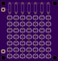
That's exactly what I was looking for. Thanks.Go to https://oshpark.com/shared_projects/rkU0U4LT pay them $17 and in about 3 weeks you'll get 3 of these at your door. This is untested, but it is hard to imagine what could go wrong.

Hi Sy
i think i have made it work, it has something to do with the grounds from my power to the ground in the centre of the 250k resistor , when psu to centre of the 250k is connected a small amount current is taken by the plate , but when you remove the ground from 250k divider the current start to flow to the plate .COULD IT MY POWER SUPPLY it is an old Radford power pack 300v@100mA..
Still learning
cheers
den
That's exactly what I was looking for. Thanks.
Note that I used the little 7mm (generally 1/8W) resistors to save space. In small values, they are getting a little tricky to source, but these should work: ERO-S2PHF4R30 Panasonic | Mouser
Hi All
I got my Edcor iron yesterday, and made a top plate. LED arrays and Maida regulators are made.
Noob question: are the 47K resistors on the EL84's really grid stoppers? Should they be carbon comp. or metal film. I know to use cc on the inout tube's grid stoppers.
Thanks
Doug
I got my Edcor iron yesterday, and made a top plate. LED arrays and Maida regulators are made.
Noob question: are the 47K resistors on the EL84's really grid stoppers? Should they be carbon comp. or metal film. I know to use cc on the inout tube's grid stoppers.
Thanks
Doug
Hi All,
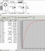
Yesterday I set up the 400 V supply to the 12AT7. 350 V Txr to Bridge to CLC (100 uf/9 H/100uf) into a 40K dummy load. I was getting 450 volts, so I put a 3300 ohm resistor in after the bridge. This brought the voltage down to 390.
My problem is when I model this in PSUD2, it takes 5 seconds to reach voltage. See attached photo. Is this OK, or what should I change.
Thanks,
Doug

I should add that the main thing is to not have the screen come up to voltage before the plate does, otherwise, the screen will think it's a plate and start drawing excessive current. And there's no issue I can find with having the plate voltage higher than normal- in fact, I've found some advantage to that.
- Home
- Amplifiers
- Tubes / Valves
- The Red Light District - another PP EL84 amp