"wasnt some parts destriod during the wireing errors then."
No I checked the integrity of all components. If one of the transistors had failed the voltage across the CCS would have collapsed to about 15V rather than the 25V it has at the moment.
" have no idea other than fiddling with the bias adustment. Set the CCS for the desired current, put a pot across the cathode resistor (if you are using one) and check if there is a change in plate voltage when adjusting the pot. At least it is easy to try..."
I don't think this will work. The reason is that there are a range of plate voltages which can marry to the cathode voltage, the plate voltage seems to want to drift sufficiently high to collapse the correct functioning of the CCS. I have it working at the moment, but its still clipping, but not so badly as before.
I have LED bias with two red LEDs, I tried shorting out one of the LED's and it had little effect on the plate voltage.
Any more suggestions would be appreciated.
Shoog
I worked out what was wrong. I had installed the transistors as if they were NPN's (ie with the Emitter and the Collector reversed). Fortunately the transistors hadn't suffered. Everything is now working. Since the Red LED's have a voltage drop of 2.1V I took out one from the reference chain. I also replaced the 2K2 with a green LED.
The plate voltage now adjusts itself to the correct point for the current set.
So it is now playing and sound good(ie not horribly distorted). However there are still a few problems. There is a resonance centered on 70hz which seems to have little to do with the parafeed cap. its about +3db.
Now that everythings working, overall it has a voltage gain of 2x which suggests a further driver stage.
The main problem is with the 5687 driver and the interstage transformer. The -3db point is at about 5Khz, this is with about 15mA through the 5687. I didn't expect transformer capacitance to be the limiting factor, rather the bottom end flaking out - which is fine.
Really the transformer needs about 30mA to drive its capacitance. The other problem is that the 5687 has headroom problems. With the 165V on the top of the CCS and a current of about 15mA, the plate has about 105V on its plate, this clips at about at about 110Vpp which gives a final output of about 15Vpp. Also in order to try to increase the current though the 5687 I drop the bias point to 2.1V, which clips well before full output. Therefore the 5687 could do with 150V on its plate with a grid bias of -4V. This would require about double the +B I have.
I would also say that the operating point I have chosen for the 6080 can only give about half of its potential output power (though i'am a little uncertain of the relationship between peak to peak input signal and bias points).
Still the circuit would be servicable if I could find a way of doubling the driver tubes +B without introducing another transformer. Is there a way of creating a voltage doubler off the same secondary as the main supply.
Shoog
Heres my latest thinking. The 5687 just won't hack it, it just can't give enough gain and current without melting.
So re-enter the ECL82, not the most ideal candidate because of it excessive gain - but I have some so I will try. My ideas to use the ECL82. Split the load on the anode of the triode to reduce the 60x gain by half. CCS load the pentode at about 35mA, but triode strap it. Run everything off the 165V supply. Attempt to use the interstage for a 2x step up( which will lower the -3db point by about a half octave at the top). Rap a bit of global negitive feedback around the interstage transformer back to a split cathode resistor in an attempt to flatten its response. Try a bit of plate to plate feedback from the triode to the triode strapped pentode.
Any thoughts on this as a way to go.
Shoog
Hi Shoog
Why are you planning to reduce the gain of the triode and than using a step-up interstage trafo? Something with maximum swing or so? - I am quite a newbie..
Bob Danielak uses an ECL82 to drive an EL509.
http://www.geocities.com/bobdanielak/technoteNo33.html
With some adaptations it would probably do a nice job driving an interstage trafo for PP 6AS7.
still so much to learn...
Erik
That OK.
The only thing I don't like with the ECL82 is that it only allows a bias point of -1.5V for 1mA through the triode - which means that its easy to clip the triode. Also with only 1mA through the Triode its not easy to apply much plate to plate feedback. If plate to plate feedback is used its possible to make an anode follower respond much like a cathode follower.
By the way uping the current through the 5687 to 25mA does improve the upper response. So far all I can get out of it is about 3.5W of power before clipping.
Shoog
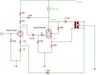
This is my design for the interstage transformer design using the ECL82. Any comments are welcome.
I had some ideas about how to overcome the limitations of the torodial interstage transformer approach. The first and obvious solution is to lower the output impedence of the driver triode. This will allow it to better drive the interwinding capacitance. Choosing a triode with high enough gain and low enough output impedence would be a problem. Alternatively simply push 40mA through the driver, but again achieveing this with only 170V of supply would be tricky.
Another solution which adds another dual triode would be to use a transformer with a step down ratio, this will have two benefits. It is likely to have lower interwinding capacitance. Secondly the step down ratio will increase the effective impedence of the load presented to the driver, by that ratio. The disadvantage is that we then need to add another pair of triodes after the transformer in order to regain the voltage we lost in the transformer. If we use a dual triode for this - mismatch shouldn't be a real issue. This could potentially introduce more distortion as we have introduced another gain stage. This however is probably the best solution overall as it stops the interstage transformer becoming the limiting factor.
The third solutions is what I am attempting, which is to lower the effective impedence of the driver so making it more able to drive the interwinding capacitance. There is plate to plate feedback which should level out the frequency response (the loading down at high frequency is present at the plate of the driver and doesn't appear within the transformer). it will also make the whole stage behave more like a cathode follower- ie lower output impedence. This is local feedback so should be stable. There is also global negative feedback which should help to reduce any distortion introduced within the transformer, and also reduce the output impedance. If the gNF proves unstable it will be removed - but the plate to plate is the important form of feedback. Because the CCS consumes 70V it should allow a voltage swing of 60V.
If this proves inadequate I will attempt a step up arrangement. If I can get the response flat to 10Khz I will be reasonably happy.
Another reason that I like my solution is that it maintains the two tube per channel idea.
Shoog
Attachments
Hi there,
I lashed up the ECL82 driver today.I made one or two simple changes. The split cathode on the triode is now made up of 630R on the top and 470R on the bottom. The anode load is 22K at the top and 33K at the bottom. Works really well. For a 2.5Vpp input I am getting about 8Watts of output. The pentode is producing about 110Vpp output which is about its theoretical limit with 65 volts over the CCS( (65-10)*2=110). At this point the input stage clips. It would therefore be pointless to try to get more output from the input triode as it would drive the pentode into clipping.
The frequency response has gone up from -3db at 4khz to -3db at 8khz, and response is sustained well beyond that point. The 70hz response peak is still there, but maybe slightly reduced. The plate to plate feedback is working and stable, the cathode feedback is working and stable. Sine wave response is good until about 8khz when it starts to look a bit odd. Square wave response seems to be a little more spiked.
There is one strange aspect in that the 6080's are giving about 2/3 of their grid input voltage as output. For some reason they are not even achieving unity gain. The cathodes are unbypassed. Would bypassing the cathodes solve this or is there another reason for the loading down. If I bypass - what value should I use?
Shoog
Probably too hi cathode degeneration ?
The sum of cathode resistors is appoximately equal to the anode load !
And the same current flows thru both.
If you drive'em with a dual widings IST, you could reference (AC only ! ) the 'cold' side of each winding to the respective cathode rather than to the ground.
If you can do that, you could also move the OPT between the 6080 cathodes and put a common bias resistor at CT.
I wonder if this kills Miller caps ?
Yves.
I think I have the solution.
The optimum plate to plate load for the operating point I have chosen is 1000ohm. The load I infact have is 1300ohm. This would account for a drop in output of about 1/4 or 1/3.
I like the idea of referencing the centre tap of the interstage to the respective cathodes of the output tubes. This presumably would introduce a bit of positive feedback for a bit more gain. Am I right ?
I have done similar on the cathode return from the primary side of the interstage and its driver pentode.
I am now getting about 8watts out in pure class A. Am I right in assuming that 50% efficiency is the max I can expect from a class A Push Pull. If so then this circuit as efficient as it can get without pushing it into class AB.
Shoog
Shoog said:I think I have the solution.
The optimum plate to plate load for the operating point I have chosen is 1000ohm. The load I infact have is 1300ohm. This would account for a drop in output of about 1/4 or 1/3.
I like the idea of referencing the centre tap of the interstage to the respective cathodes of the output tubes. This presumably would introduce a bit of positive feedback for a bit more gain. Am I right ?
At least, this remove negative feed back from unbypassed cathodes.
I have done similar on the cathode return from the primary side of the interstage and its driver pentode.
I am now getting about 8watts out in pure class A. Am I right in assuming that 50% efficiency is the max I can expect from a class A Push Pull. If so then this circuit as efficient as it can get without pushing it into class AB.
Look acceptable to me !
Yves.
I just wanted to correct some statements I have made.
The drive to the 6080's is 60Vpp which gives a final output of 5.5Vpp. This should give about 7.5Watts of clean output in 4ohm load.
The measurements I stated before were down to problems with interpreting my scope. I apologies for any misunderstanding.
Shoog
The drive to the 6080's is 60Vpp which gives a final output of 5.5Vpp. This should give about 7.5Watts of clean output in 4ohm load.
The measurements I stated before were down to problems with interpreting my scope. I apologies for any misunderstanding.
Shoog
Did you mean 5.5vpk or 5.5Vpk-pk, there's a world of difference between the two..  By my calculations 5.5Vpk into 4 ohms is about 3.75Wrms..
I recommend either adding cathode bypass capacitors or alternatively a bipolar/non-polar cap between the cathodes of the 6080. Right now your unbypassed cathodes are reducing gain to less than 1 and also increasing rp to something like 1.3K if I haven't goofed the calculation.
You'll get at least twice the power, better bass extension due to the lower effective rp, and less distortion for the same reason at low frequencies.
I suggest trying a cap across the 6080 cathodes because in theory this will make the output pair a cheesy LTP and should result in some additional cancelation of even harmonics, and the net dc voltage difference will be small as will be the ac voltage across the cap as long as Xc is relatively small compared to the resistance present at the cathodes. I would think a 63V-75V cap would be adequate here which is good because it will need to be big to be effective - several hundred uF minimum. Something to try anyway, you may or may not like the results.. Bass performance would probably be better with straight cathode bypass caps.
By my calculations 5.5Vpk into 4 ohms is about 3.75Wrms.. I recommend either adding cathode bypass capacitors or alternatively a bipolar/non-polar cap between the cathodes of the 6080. Right now your unbypassed cathodes are reducing gain to less than 1 and also increasing rp to something like 1.3K if I haven't goofed the calculation.
You'll get at least twice the power, better bass extension due to the lower effective rp, and less distortion for the same reason at low frequencies.
I suggest trying a cap across the 6080 cathodes because in theory this will make the output pair a cheesy LTP and should result in some additional cancelation of even harmonics, and the net dc voltage difference will be small as will be the ac voltage across the cap as long as Xc is relatively small compared to the resistance present at the cathodes. I would think a 63V-75V cap would be adequate here which is good because it will need to be big to be effective - several hundred uF minimum. Something to try anyway, you may or may not like the results.. Bass performance would probably be better with straight cathode bypass caps.
Thanks for that analysis. I was think that I was going to add cathode bypasses. I did a little experiment by adding 1000uf caps. The gain went up to just less than unity and the sound seemed to open up somewhat. Because of the high dissapation through the 330R cathode resistor I had to use wire wound, which seems to effect the high frequency response. I will bypass with 1000uf 63V electros paralleled with 10uf 63V polys.
Starting drilling the case. Will be about a week before I can test anything again.
Shoog
Starting drilling the case. Will be about a week before I can test anything again.
Shoog
I'm looking at a hybrid design with an interstage phase splitter. Since you are cap coupled, you don't need a transformer, an autoformer will do. Should be easier to get wide response, especially if you can go 1:1 with the drive voltage. How about a center tapped choke? Connect both driver and opt grids to each end, R load across the ends, and ct to ground or bias.
Sheldon
Sheldon
Sheldon,
The autotransformer idea sound interesting. Care to sketch me a plan as i'am having a little difficulty visualising your scheme.
The only thing I would be concerned about is the unused primary of the toroidals I have. In my small experience an unterminated winding tends to ring with large intermodulation distortion as a result.
Shoog
- Status
- This old topic is closed. If you want to reopen this topic, contact a moderator using the "Report Post" button.
- Home
- Amplifiers
- Tubes / Valves
- Idea for a 2 tube 6080 PP amp.