ERRATA CORRIGE:
substitute R17 with a red led and fix R16 accordingly to have 2 mA through the leds. This increases linearity, especially at higher frequencies.
substitute R17 with a red led and fix R16 accordingly to have 2 mA through the leds. This increases linearity, especially at higher frequencies.
Code:
B- [V]	R17          	R16 [kOhm]
15	red led    	5,8
20	red led    	8,3
25	red led    	10,8
30	red led    	13,3
35	red led    	15,8
40	red led    	18,3
45	red led    	20,8
50	red led    	23,3
55	red led    	25,8
60	red led    	28,3
65	red led    	30,8
70	red led    	33,3
75	red led    	35,8
80	red led    	38,3
85	red led    	40,8
90	red led    	43,3
95	red led    	45,8
100	red led    	48,3
105	red led    	50,8
110	red led    	53,3
115	red led    	55,8
120	red led    	58,3
125	red led    	60,8
130	red led    	63,3
135	red led    	65,8
140	red led    	68,3
145	red led    	70,8
150 red led 73,3As I've done for the EL34 version, I do the same for the EL84.
Has anybody experience with these output transformers?
Hammond 1608: 8kRaa, 10W, max 100mA, less than 70€.
Loadline stays below max plate dissipation at B+ 250V and 45mA, with a bit more than 8Wrms in class A1.
Hammond 1609: 10kRaa, 10W, max 100mA, less than 70€.
Loadline stays below max plate dissipation at B+ 260V and 42mA, with a bit more than 8Wrms in class AB1.
Hammond 1620: 6k6Raa, 20W, max 158mA, less than 90€.
Loadline goes close to max dc current with B+ 330V and 30mA, with a bit more than 16Wrms in class AB1.
Hammond 1650F: 7k6Raa, 25W, max 128mA, less than 90€.
Loadline goes close to max dc current with B+ 330V and 30mA, with a bit more than 16Wrms in class AB1.
Hammond 1650E: 8kRaa, 25W, max 100mA, less than 90€.
Loadline goes close to max dc current with B+ 270V and 40mA, with around 10Wrms in class AB1.
Just as a side note, I've ordered two custom OTP with 23%UL and 8k Raa running at around 320-330Vdc (Mullard datasheet suggested 6k6 with 23% UL but with a lower B+).
Hi,
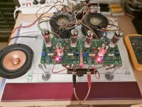
I've used a Hammond 1650FA recently on a Tubelab SPP, wired as UL.
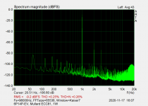
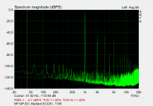
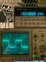
The 10Khz square wave is a bit ugly even with gNFB, but otherwise the amp measures nicely, FR is pretty flat from 20Hz to 20Khz and I really like the sound. Bass is solid with my Klipsch Quartet speakers (IMHO).
I've used a Hammond 1650FA recently on a Tubelab SPP, wired as UL.
The 10Khz square wave is a bit ugly even with gNFB, but otherwise the amp measures nicely, FR is pretty flat from 20Hz to 20Khz and I really like the sound. Bass is solid with my Klipsch Quartet speakers (IMHO).
Attachments
Good Job!
Looks great!
The 10k square wave appears to show a small resonance at about 35kHz.
Do not worry too much over that . . .
A transformer resonance at about 35kHz, as you have, should not be a problem,
as long as the negative feedback is stable when loaded by your speaker cable's capacitance plus your speaker's reactances.
Most music does not contain a lot of 35kHz signal to activate that resonance, and most speakers do not have any response there, and most human ears do not work well there either.
Enjoy listening tonight, and then get a good worry free sleep.
“Those who do not know history, are not aware that Deja Vu is here again”
Last edited:
Sad news about Marc. RIP
This is a cross post of the announcement on EL34 Baby Huey thread:
https://www.diyaudio.com/forums/tubes-valves/326920-el34-baby-huey-amplifier-92.html#post6432220
This is a cross post of the announcement on EL34 Baby Huey thread:
https://www.diyaudio.com/forums/tubes-valves/326920-el34-baby-huey-amplifier-92.html#post6432220
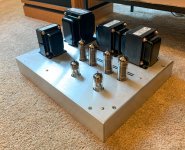
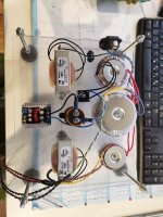
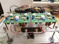
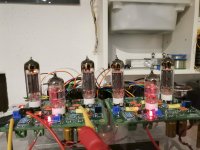
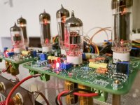
It's alive, sounding good, needs time for some objective and evaluating listening, but sounding nice... 330VDC plate and 36mA bias. For now is still in a prototype form, need to build an enclosure in the future.
Attachments
Last edited:
Nice looking! It will be more linear if you substitute R16 and R17 as shown on this post:
EL84 Amp - Baby Huey
This is a gingertube suggestion.
EL84 Amp - Baby Huey
This is a gingertube suggestion.
") Do you do this only after the amp is built according to the tolerances of the parts in the amp? Where do you attach the probe leads and what are the expected voltages?
Do you do this only after the amp is built according to the tolerances of the parts in the amp? Where do you attach the probe leads and what are the expected voltages?You have a negative DC voltage on the bottom of the PI's CCS.
That depends on the voltage you set the negative rail at.
The two leds are referred to ground on the positive side, and to the negative rail on the negative side. The differences between the two, minus 1,7V of the first led, minus 1,7V of the second led, divided by 0,002 A give you the needed resistance you need to use to set the led current to 2 mA.
Where to measure the B-
on C10 I have -64,2V but on C11 I have 73V, witch one to chose.
on C10 I have -64,2V but on C11 I have 73V, witch one to chose.
ERRATA CORRIGE:
substitute R17 with a red led and fix R16 accordingly to have 2 mA through the leds. This increases linearity, especially at higher frequencies.
Code:B- [V] R17 R16 [kOhm] 15 red led 5,8 20 red led 8,3 25 red led 10,8 30 red led 13,3 35 red led 15,8 40 red led 18,3 45 red led 20,8 50 red led 23,3 55 red led 25,8 60 red led 28,3 65 red led 30,8 70 red led 33,3 75 red led 35,8 80 red led 38,3 85 red led 40,8 90 red led 43,3 95 red led 45,8 100 red led 48,3 105 red led 50,8 110 red led 53,3 115 red led 55,8 120 red led 58,3 125 red led 60,8 130 red led 63,3 135 red led 65,8 140 red led 68,3 145 red led 70,8 150 red led 73,3
- Home
- Amplifiers
- Tubes / Valves
- EL84 Amp - Baby Huey