Guys,
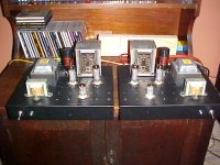
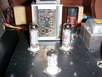
My lastest Baby picture. Monoblocks.
Fixed bias, choke input power supply, SS rectifier, MOSFET (ZVN0545A) source followers AC coupled off the diff amp and the output tube grids direct coupled to the MOSFET sources pins. Output tube bias is applied at the MOSFET gates.
Cheers,
Ian
My lastest Baby picture. Monoblocks.
Fixed bias, choke input power supply, SS rectifier, MOSFET (ZVN0545A) source followers AC coupled off the diff amp and the output tube grids direct coupled to the MOSFET sources pins. Output tube bias is applied at the MOSFET gates.
Cheers,
Ian
Attachments
And for Chrish and other "Downunder" tube nutters.
Dig those A&R Vintage Output Trannies made in Melbourne. I pulled some Hammond 1608 to put these in - much better.
And so as to not start that Sydney vs Melbourne mudslinging (being from Adelaide I'm above that) , the power trannies are Vintage Trimax from Sydney.
Cheers,
Ian
Dig those A&R Vintage Output Trannies made in Melbourne. I pulled some Hammond 1608 to put these in - much better.
And so as to not start that Sydney vs Melbourne mudslinging (being from Adelaide I'm above that) , the power trannies are Vintage Trimax from Sydney.
Cheers,
Ian
Attachments
Baby Huey Sings!
Finished wiring up "Baby Huey" Last night at about 1:30am, but it did not work
Left channel had a shorted out shield from the feedback. Fixed that, but was getting some nasty AC on the output of the coupling capacitor of that channel. Thought it might have been a faulty coupling cap (using Russian), so replaced - still same problem. Output from input tubes was OK when power tubes removed - kept looking for problems... Turned out that one of the output tubes was bad maybe from the shorted feedback shield. Had plenty of replacements as I am using 6P15P and 6P14P output tubes and 6N2P driver tubes purchased in bulk.
Anyway, working now. My modelling of the power supply was a little out, voltages a bit low. Not a real problem, I can change some resistor values and use GZ34 rectifier instead of the 5U4G. More to fiddle with in the future, but at least the basics are sorted.
No matter how hard I try, my patience gets the best of me and I can never get my wiring as neat as I would like
Guess an appropriate CD for the first listening test!
Nice work with the amps Ian. Speaking of transformers, in a weak moment on my last work trip to Singapore I bought a pair of these:
I have some Russian 6L6GTs, 6SN7s and 6SL7s that need to be used too....
Cheers!
Chris
Finished wiring up "Baby Huey" Last night at about 1:30am, but it did not work
Left channel had a shorted out shield from the feedback. Fixed that, but was getting some nasty AC on the output of the coupling capacitor of that channel. Thought it might have been a faulty coupling cap (using Russian), so replaced - still same problem. Output from input tubes was OK when power tubes removed - kept looking for problems... Turned out that one of the output tubes was bad maybe from the shorted feedback shield. Had plenty of replacements as I am using 6P15P and 6P14P output tubes and 6N2P driver tubes purchased in bulk.
Anyway, working now. My modelling of the power supply was a little out, voltages a bit low. Not a real problem, I can change some resistor values and use GZ34 rectifier instead of the 5U4G. More to fiddle with in the future, but at least the basics are sorted.
No matter how hard I try, my patience gets the best of me and I can never get my wiring as neat as I would like
An externally hosted image should be here but it was not working when we last tested it.
Guess an appropriate CD for the first listening test!
An externally hosted image should be here but it was not working when we last tested it.
Nice work with the amps Ian. Speaking of transformers, in a weak moment on my last work trip to Singapore I bought a pair of these:
An externally hosted image should be here but it was not working when we last tested it.
I have some Russian 6L6GTs, 6SN7s and 6SL7s that need to be used too....
Cheers!
Chris
Thanks Ian,
Have not done any serious listening tests yet, kids were complaining when I had my standard test tracks paying before dinner. I know that I have to sort out the voltages. I am using a valve rectifier and used PSU11 to model the power supply. I was worried my voltages would be too high, so from the rectifier I have used 32uF cap - 10H choke - 32uF - 60R 10W -200uF - 180R - 80uF motor run cap (80uF motor run is the 100uF cap shown at the output transformer in the schematic). I am just about to check the voltages with a GZ34 in place of the 5U4G that I had in it for testing.
Will give a better run down on the sound when I have sorted out the voltages, but I can say that I am happy so far and that it is hum, hiss and buzz free! It does sound different from my SE amps and better than my only other PP project (a cheap and simple 6BM8 posted in previous threads here).
B+ with a GZ34 is 308 volts, not bad. Voltage at the input tubes is still a little low, around 145 volts, I think 170 volts is what is planned. Will have to work on it later.
Just a note, this is my 5th project using Edcor output transformers (project 4 used project 2s salvaged small 10 watt PP transformers). For the first 4 I followed the Edcor schematic for the connection of the feedback. For the first 4 I had to reverse the phase! This is the first using he enclosed XPP transformers, but I took a hunch and wired it up backwards to the schematic and it worked first up. I think TubeLab noted on his web site that when he wired up the Edcors they were out of phase compared to their schematic.
Cheers,
Chris
Quick question re my amp.
I have on hand a few 6P15P (Russian EL83 equiv) and 6P14P (Russian EL84 equiv). I built this amp with the intention of being able to use either valve. Accordingly, I have put a bridge between pins 1 and 3 on the power valve sockets, as the 6P15P does not have an internal connection between the cathode and G3.
Have noticed that one channel might be a little unstable/oscillate with the 5P15P when I was checking things on the bench, but got no further than noticing there were no problems with the '14Ps. This might not have actually been the case, as I was fixing a couple of very minor things at the time. Anyway, I have read that the 6P15P has a slightly more fragile G2 than the '14P (1.5Watts v 2.2 watts) and care should be taken when substituting them for an EL84. The original schematic calls for 33R grid stoppers on the g2 pins. Should I try a higher value, say 1K? Would this adversely affect the performance?
Sorry for the questions, don't have enough time to experiment or do empirically right now as I am in the middle of university assignments (as well as working and being a part-time single dad...). Chewed up more time than I should have just building the thing!
Thanks,
Chris
EDIT: Just plugged some '15Ps in, and it seams to be playing OK, but still wondering if it might be prudent to increase the g2 resistor.
Cheers...
Chris,
Yes - increase the G2 Grid Stoppers. I'm posting my monoblock schematic in a few minutes. You will see I used 150R. I would try 220R and 470R before going to 1K. Only make it as large as necessary to kill any parasitic oscillation. Of course you should make sure you have adequate grid stopper on Grid 1 first (4K7 is what I use).
Adjusting the G2 stopper resistor (Screen resistor) is a common guitar amp hacker thing. If you want a guitar amp to start to distort at lower power/volume levels you massively increase the screen resistor. Thats why I say, for HiFi only make it as large as you need to.
Cheers,
Ian
All,
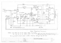
Here is my newest "Baby Huey" monoblock. Power supply not shown.
The source followers I believe make the amp sound much more powerful. They act (in combination with fixed bias) to eliminate any blocking distortion. It also isolates the load on the diffamp and will allow the shunt feedback to be slightly more effective.
The 350V rail means that the thig develops nearly 12 Watts - I was using Hammond 1608 (10 Watt rated) Output transformers but core saturaion was evident at anything below about 35Hz. Changing to the Vintage A&R transformers (core about 50% larger) made the amp sound cleaner and more powerful. The A&R also had a better top end. Having said that the Hammond 1608 sounded very respectable. With a 300 or 320V HV rail I prbably would have left the Hammond in. With 350V I'm developing just a little bit too much power for it and the bigger core tranny helped.
The power supply is not shown.
+350V comes from a 285-0-285 @100mA secondary. 3A Ultrafast diodes with 10nF 3kV ceramics across them, into 5uF/900V polyproylene, thru a 2H 200mA choke to a 470uF/500V electrolytic with another 5uF polyproylene across the electrolytic. (Note I originally had a Hammond 8H 100mA choke here, going to the 2H 200mA choke I though cleared up a little "muddiness")
+75V comes from the +350V. 68K/2W to a 75V 1.5W zener, 22uF/100V and 2u2 100V poly propylene filter caps across the zener. A 30V or 36V zener would do. You just want to keep at least +25V on the drains of the MOSFETs. 75V Zener is just what I happened to have in my parts bin.
EL84 heaters off a 6.3V @1.5A winding
Not enough currentt capability to also run the 12AX7 heater BUT there was a 5V @2A winding. I bridge rectified that using Schottky Diodes and a 10,000uF to get 5.95V DC. Close enough. I connected the -ve side of that to the +75V rail. This reduced noise a little.
The negative (-45V) rail uses a separate transformer. A 18-0-18 @ 1A. I left the CT unconnected and used Ultrafast Soft recovery diode bridge across the full winding. That gave me 52 Volts. I inserted a 220R resistor between the diode bridge and the filter cap to drop that to 45V so that I could use a 470uF/50V Blackgate electrolytic which I had on hand. The series resistor and the Blackgate both help to keep that -45 rail squeeky clean.
Cheers,
Ian
Attachments
Impressive, Ian. Thank you for posting.
Do you think that constant current sources on the sources of the mosfets would reduce Vgs distortion further? Would it be worth it? The way I see it there is a chance this could decrease odd order distortion, and slightly lessen compressive distortion at higher output.
Really like the tiny cap coupling on the mosfet gates, and the direct source coupling to the EL84 grids. Wonderful design!
Thoughts?
Hugh,
I'm almost certain that CCS loading of the MOSFET Source Followers would give some benefits. Whether it would be noticable or not - who knows. As you would apreciate there comes a point where the "simple design" suddenly is not so simple any more and you have to decide whether to finese the design for ever or to draw a line in the sand and say that is it. I've basically done that with this design. Its providing lovely music while I get on with the next project. A total braek from "Baby Huey". I've had some Plitron PAT 4006 Toroidal Output trannies (Raa 1885:5 Ohms, 100W, full power bandwidth 27Hz to 235kHz) sitting on the shelf for about 4 years. I've ordered a couple of quads of 300B. So I'm in the pencil and paper stage of a couple of parallel push pull 300B monoblocks. They (I hope) will be my next step up in the audio nivarna quest.
And my reference amps - Your AKSA Lifeforce 55, naturally.
Cheers,
Ian
Hi Ian,
Your last implementation opens a wide door to paralleling output tubes !
Great.
Cheers, Yves.
gingertube said:. . .
As you would apreciate there comes a point where the "simple design" suddenly is not so simple any more and you have to decide whether to finese the design for ever or to draw a line in the sand and say that is it.
Ian
Your last implementation opens a wide door to paralleling output tubes !
Great.
Cheers, Yves.
Hi Ian,
Another thought....
The Zout of the mosfets is so low that you could actually indulge a little RF design here. You could ground the grids of the EL84s, and drive the tubes from the cathodes!!
As you know, this increases bandwidth and speed, and reduces distortion further still. AND, it would be unique.....
Say, my LF55 the reference!! That's really something, thank you!
Cheers,
Hugh
Baby-Huey Monoblock
Hi, Ian
Another impressive circuit !! thanks..
Two things.
1. the adjusting pot connecting CCS and 12ax7 cathode is gone.. I really like the adjusting pot which helps to produce sharp music image.
2. the B+ now is 350V..about 15% above the EL84's 300V spec. Likely is ok judging from my Dynaco sca-35 (now my baby-huey) was running even higher voltage sometimes.
Cheers
JueiC
The "Balance" adjustment pot can be put back in and if you are using modern production ECC803S or 12AX7A where the two triodes are not necessarily well matched it is probably a good idea to do so.
For this build I used selected NOS Philips 12AX7A where the two triodes were matched perfectly and so did'nt need the balancing function - BUT I am now limited to using selected 12AX7s.
The JJ EL84 I'm using cope with 350V OK although you may note I pushed the screen resistors up from 33R to 150R as a precaution.
350V is just what I ended up getting with the power transformers I had. 300 to 320V would be better and a Hammond 1608 Output Tranny would cope better (it drops output power back to wiyhin the 10W rating).
Cheers,
Ian
Ian,
I've just finished the original baby huey for about 3 weeks and enjoy very much with it. Great design for a newbie like me. But, all in a sudden you have another design coming up with fixed bias. Oh!!! it makes me ichy and eager to try, since the first one is so good and I suppose the fixed bias should be much better.
1). Can you tell me how you find ( sound wise ) between the two.
2). That two 50k pot is just for adjusting -12v for the G1 of the EL84. Am I right?
3). The test point showed at the cathode of both EL84, Is it just the check point for checking the 'Voltage', and or we have to make some adjustment here? and how?
4). Do we need any heatsink for the mosfet?
I know you like this design very much and I still believe you'd make some kind of tweaks so to improve it's performance. Should I wait a bit until you have the performance maximized ?
Thanks
Albert
Albert,
The fixed bias version is a little bit better when driven hard - this is because it doesn't suffer from blocking distortion which is a problem with most cathode biased amps.
The test points shown in the new schematic are to measure the voltage across the 10 Ohm "current sense" resistors in the EL84 cathodes. You then adjust the 50K pots (with no input signal) to get 0.4 Volts at the test points - which means that you have 40mA of idle current. The voltages at the mosfet cathodes will be approximately -12V (between -10 and -14 volts).
ALL - Mods to the new schematic.
Extended listening showed that the amps were a little "slow" with respect to PRAT (Pace, Rhythm and Attack). Dropping the feedback resistor from 20K back to 15K (the value used in the original) fixed that.
A quick calc of the coupling capacitors. 10nF into 1M2 gives a low frequency corner at 13.3 Hz. I decided to double the caps to 22nF to shift this down to 6Hz. I don't know if I really noticed any difference in the sound to be perfectly honest. Theory says it should be better with 22nF caps instead of 10nF but the output tranny low frequency response is probably preventing me from noting any real difference.
So if building from scratch use the 22nF. If you've already built it with 10nF I don't think its worth changing.
Cheers,
Ian
- Home
- Amplifiers
- Tubes / Valves
- EL84 Amp - Baby Huey