Latest Baby picture.
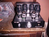
6SL7 and 6V6G
The Chassis and Tranny Cover are from Mabel. This is the full version with CCS loaded MOSFET Source Followers, Fixed bias outputs. Construction into this tiny chassis was a serious pain but I got there in the end. For 6V6 I've chnged the 47K:15K:47K shunt feedback to 39K:18K:39K, the lower (than EL84) gm output tubes need a little more local shunt feedback.
Cheers,
Ian
Attachments
Dan,
This has "Bog Standard" Hammond 1608 Output Trannies.
I had friends around for drinks last Friday evening just after I'd done the final tweak of the feedback level and the response was not "how soon can you build another one for us" BUT rather "how soon can you build another one for yourself, We want this one".
No kidding - its sounds seriously gorgeous. I'd been listening to some JADIS JA80 80W Class A mono-blocks I'd just finished re-tubing for a local audio nutter, it was a massive relief to get rid of them and fire this up instead.
Some of that gorgeousness comes from the 6V6Gs (Sydney Australia factory AWV circa 1960) but I've also run it with 1980's Russian military 6V6 (the big box they came in still had the KGB stickers on the side) and it was almost as lovely with those.
Cheers,
Ian
Last edited:
Baby Heuy 6SL7/6V6 Version
Gingertube
Referring back to Page 1 of this thread you stated:
"As a practical exersize I have built a 6SL7 plus fixed biased 6V6G experimental version but low 6V6G Rg1 requirement (imposed by the fixed bias), lower 6V6 gm, higher currents for the 6SL7 etc. have meant that it just isn't in the same league - I keep running into limiting conditions everywhere as parametrers are pushed outside of acceptable limits"
How then (apart from different feedback resistor values) did your new 6SL7/6V6 version overcoming the design limitations?
I still run both 6V6 and EL84 Baby Hueys. The higher gm EL84 is theoretically the better choice but in practice all of the 6V6 BHs have been lovely and there is not a lot to pick between them. The EL84 is probably still better across all music selections, 6V6 are rock and blues tubes. I use these same 6V6G in Guitar Amps I build.
Ejam,
All of the 6SL7 / 6V6 BHs are the latter circuit incorporating MOSFET Source Followers. 6V6 grids are direct coupled to the Source Follower Outputs and Fixed bias is applied to the MOSFET gates. That addresses those problems noted back on page 1. The schematic is pretty much like that of post 602 on page 61, feedback mod as stated above, Mosfet Source Follower currents increased to 3mA. Note the "corrected" schematic at post 604 (f/b from UL taps instead) was abandonned after further listening.
I'm not sure what the next amp will be at this point - you see I have these piles of bits:
Pile 1: Power and Output Trannies, Chokes, Chassis Tubes etc. for 845 SE Stereo
Pile 2: Plitron Power and Output Trannies, Chokes, Chassis and 2 quads of EH300B for PPP Monoblocks
Pile 3: Plitron Power and Output Trannies and 2 quads of Gold Lion KT88 for PPP Ultralinear + Cathode Feedback Mono Blocks.
Pile 4: 2 EL84 BH Monoblocks part dissassembled to have their diff amps rebuilt with 6BR7 pentodes.
Decissions, decissions !!!
Cheers,
Ian
Last edited:
Actually I do know what the next project is - my preamp needs an update before any new power amp is started.
This will be a Vaccum State SP2, no doubt "compromised" by using a remote control channel selection and motorised Alps Volume Pot. Super Reg will be used.
Cheers,
Ian
This will be a Vaccum State SP2, no doubt "compromised" by using a remote control channel selection and motorised Alps Volume Pot. Super Reg will be used.
Cheers,
Ian
Pile 4: 2 EL84 BH Monoblocks part dissassembled to have their diff amps rebuilt with 6BR7 pentodes.
This is something I hope you get around to one day as I would love to have a go at building it. In the meantime my chip phono preamp also needs updating so I suppose that'll keep me busy until then......
")
Brgds Bill
I second the vote for "Pile 4" !
I've collected all the parts for my Baby Huey build. Got the iron (James), made up the CCS and SF modules, got the EL84s. Then Ian mentions that using pentodes in the diff amp may be worth persuing! I'm stalled, not wanting to pull the trigger just yet
Come on, Ian, I need some closure
Luckily I have been distracted by a pre-amp project - Vacuum State FVP5A
Hi Ian. Sorry in case the question was already answered. Way too long a thread. 
Have you tryed it that way too?
for the sake of curiosity. Given that you use local NFB a la a "Schadeode", why have you connected the g2 to the UL tap instead of a fixed voltage as is done in original Schadeode?The schematic is pretty much like that of post 602 on page 61, feedback mod as stated above,
Have you tryed it that way too?
UnixMan,
I haven't tried any of the Baby Hueys withe Pentode Mode Output Tubes, I have always added Ultralinear connections into the mix.
That is purely so that I can avoid using any global feedback.
The original circuit on which all the BH's are based is by Yves Monmagnon (Yvesm) and he did use pentode mode with global feedback.
See post 504 on page 54 for Yves circuit using 6GW8 (ECL86).
Cheers,
Ian
I wonder if there is any difference. With Schadeode, the closed-loop gain of the output stage is fixed by the ratio of the divider formed by the NFB resistor and the output impedance of the driver stage. Using UL, you reduce the gain of the output tube WRT the same tube used in plain pentode mode, so basically you add some local NFB via g2 (UL) but remove some (same amount?) from the "Schade" loop. The other way 'round if using pentode mode.
I have not done any math to check wether there is any net difference in the total amount of (local) NFB in either case, but I guess there is likely none.
On the other end, avoiding UL (via OPT tap) should avoid the phase-shifts introduced by the OPT, thus in principle the Schade local NFB loop should work better than the UL... :-?
Last edited:
well, no.A bit "tongue in check" - Both methodologies linearise the output tubes and reduce rp. So using both together should be twice as good as either alone - right?
 It's quite the contrary!
Both UL and Schadeode are just two different methods of applying (local) NFB. UL applies some local NFB via g2, Schadeode does the same via g1.
From NFB theory, the amount of linearization and output impedance reduction gained with NFB is proportional to the amount of NFB applied; that is, to the amount of "gain reduction" devoted to NFB.
With Schadeode (as far as you have enough open loop gain) you reduce the overall (closed-loop) gain to a fixed ratio, which is set by the divider formed by the feed-back R and the eq. output impedance of the driver stage.
If you use UL, the open-loop gain reduces to the gain of the tube in UL mode, which is much less than the gain of the same tube used in pentode mode (that gain difference is what gives you the gain in term of linearity and rp reduction of the UL).
So, what you get with Schadeode+UL looks like a couple of nested NFB loops.
BUT! the total open-loop gain available is always the same: it is the gain of the tube when used in pentode mode.
Again from NFB theory it can be demonstrated that, for a given amount of total gain available, a single overall loop (in this case plain Schadeode) is more effective than a number of nested loops (in this case UL+Schadeode).
Thus UL+Schadeode is definitely worse than just plain Schadeode (pentode mode). At least from a "numerical" point of view.
Whether that's also better from a sound quality point of view is another story. Parameters like THD and output impedance do have little (if any) correlation with the perceived sound quality.
To determine which way does actually sound better you need to try and listen for yourself...
Last edited:
The BH design has evolved over time by pure listening. Sure I looked at the theory and what might happen if I did this or that but the determining thing for what stayed in and what was rejected was based on just listening tests not measurements (this was a deliberate policy - I could have done all the measurements, after all I'm a Electronic Design Eng. in the day job, but I went this way based upon the fact that there appears to be very little correlation between what sounds good and the sort of measurements which are "traditionally" done, i.e. THD etc).
Cheers,
Ian
Edit: from post #1015
Last edited:
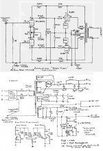
I was curious after the Baby Huey EL84 so I build it. But without global feedback. I have removed R1 and R2 and connect the lower 1K resistor to earth. See picture. I hoop this is all right.
But nevertheless I encounter a problem. Ik have an oscillation of 250KHz on the anode (and UL connection) of the EL84. Input signal is 0V. If I load the LS output with an 8 ohm resistor or lower the oscillation is gone. To me this is not good and the amp seems to be a bit unstable.
Have I done something wrong? Must the grid of the lower ECC803 connected to earth with a resistor of 1M?
BTW, in triode connection I don't have this oscillation problem.
Thanks in advance.
Regards,
René
Attachments
Rene,
Your changes should be fine.
To get rid of the oscillation in Ultralinear Mode you will need to increase the 150 Ohm screen resistors. These have a grid stop function and the body of the resitors need to be hard up against the tube pin for the screen connection. Try 470 Ohms or even 1K in lieu of the 150 Ohms. That should fix it.
Cheers,
Ian
- Home
- Amplifiers
- Tubes / Valves
- EL84 Amp - Baby Huey