]
In the mean time I have finally en enclosed amplifier based on the EL84 version of the Baby Huey")
Hi Marc,
Nice amp you got there - congratulations!
What are the voltage and ampere ratings of the toroidal transformer you are using in this version?
Hi zman,
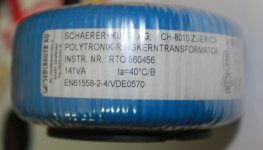
The transformer it a custom version made long time ago (October 2002) with 250 V AC@300 mA, 50 V AC@50 mA and 9 V AC@8 A output voltages with a total power of 141 VA. It is enough to power the EL84 version as well as the 6V6, 6L6 or even my 6CA7 version...
However for new project with EL34, 6CA7 or KT88 I recommend the following Toroidy TSTA 0250/001 standard transformer : TSTA 0250/001 - Mains transformer for tubes - Shop Toroidy.pl The supreme version is more expensive but is very nice
Hi jorge,
Sorry to hear that your amplifier still doesn't work I suggest that you continue this discussion on the technical EL84 Baby Huey forum where more people can help you : EL84 Amp - Baby Huey
Regards,
Marc
The transformer it a custom version made long time ago (October 2002) with 250 V AC@300 mA, 50 V AC@50 mA and 9 V AC@8 A output voltages with a total power of 141 VA. It is enough to power the EL84 version as well as the 6V6, 6L6 or even my 6CA7 version...
However for new project with EL34, 6CA7 or KT88 I recommend the following Toroidy TSTA 0250/001 standard transformer : TSTA 0250/001 - Mains transformer for tubes - Shop Toroidy.pl The supreme version is more expensive but is very nice
Hi jorge,
Sorry to hear that your amplifier still doesn't work
I suggest that you continue this discussion on the technical EL84 Baby Huey forum where more people can help you : EL84 Amp - Baby Huey Regards,
Marc
Attachments
drive tube options:
I am just doing the drilling work on my chassis plate right now. I was hoping to keep options open for diferent drive tubes. Then I realized I did not know what the options are other than 12ax7. Could some one help me out here? I was hoping to acommodate as many 9 pin or 7 pin tubes as was reasonable. with a selector switch.
Thanks for the help.
Hi,
There is really not so many option for the input tube, as explained by Ian in the beginning of this thread, the Baby Huey require a high gain tube for the differential stage and the 12AX7 with a value of u = 100 will be perfect for that.
This design with octal sockets for output tubes give you interesting possibilities to test different output tubes, but I don't see real need to test others input tubes since it is working very well with the 12AX7
Rgds,
Marc
Okay thanks for starting the discussion.
The tubes i was considering are 12bz7, 6eu7, 6ev7, 7025, 5751. Do these hold any potential for experimentation. I have learned the tube must have a min of 8 connections to be a twin triode. So either 8 pin or 9 pin tubes can be considered. I am trying to decide if I should also allow space for additional sockets. What parameters should I be focused on to help me decide.
Thanks for the help
Hi SCD,
A 12AX7A is the exact same tube as a 7025. The 12AX7 with no suffix isn't as quiet as the 7025. The 6EU7 is a great tube and was designed for the first audio amplifier for microphones and other very low level signal applications. It has even lower hum plus a shield between the sections. It has exactly the same characteristics as a 12AX7A/7025. The 5751 has lower gain and different plate characteristics. I haven't seen a 6EV7 in audio circuits before.
The thing is, you have to use a tube that the circuit was designed for (same plate characteristics) or you will likely have higher distortion and lower gain. Keep in mind that the 6EU7 has a different pinout than the 12AX7A/6EU7 does, so you'd have to rewire the socket to test this one. They are also expensive.
-Chris
Problem
Hi,
I’ve built the amp and it is impossible to bias it, the led flashes and a pulsating sound appears at the speakers.
Probably was my fault connecting the bias supply (I thought that as it was ac, no polarity should be considered ) causing a short due to one of the legs is tied to ground.
If this was the case, which parts could be damaged?
Regards,
Jorge
Okay Thanks Chris:
I will build as designed and go from there. I think there is room for options. I have room for another 9pin base if I want to broaden the selection.
Jorge:
I suggest you double check your work so far. You may have one of your diodes in wrong, or a polarity backwards. If you can, use a variable power supply to power up and check at various voltages along the way.
Close up pictures will be helpful so the experienced guys can review your work and offer suggestions.
I hope this helps
Hi Jorge,
If you make a wrong connexion to the bias voltage, it make a short circuit on the 50 V output of the transformer therefor there is no voltage on the bias circuit and no part should have been damaged here, however the transformer may have suffered from this, you have to check it !
This also happened to me when we put the EL84 amplifier (which is basically the same design with noval sockets) in the chassis and as soon I have found the error I corrected it and the amplifier was working immediately
Good luck,
Marc
Hi Marc and others...
I checked the transformer and I think it is ok with 48-49 Volts under load.
Talking about the wiring, I made the connection correctly after reading your posted message. This is how I´ve done it. If you think about the Bias connector, there is a left side and a right side, so I connected both left sides to one wire of the transformer output and the right sides to the other wire left of the transformer output. Is this the correct way?
If I understand correctly, there should be no harm to connect it wrong? How to check the health of the transformer?
Regards,
Jorge
Hi Jorge,
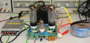
I assume that the two small modules with 3 digits display are two DC/DC power supply for the heaters of each channel and the green and orange wire are the high voltage and the 48 V coming from the power transformer, therefor what is the reason for the switching power supply in the bottom ?
It seem also that you are using this TOROIDY transformer https://www.tme.eu/en/Document/77cb69431827fb306b0301de1db87389/ENG_KT88_PP.pdf and the connection is OK
If your power transformer give you 49 V it is OK because in case of short circuit if there is too much current " l'enroulement" (I don't know the english word !) will burn and will be cut !
I really don't understand why you have this problem, your boards look nice and I don't see any big mistake ??? May be you can try to connect the feedback to avoid any instability, but this do not explain why you cannot change the bias with the trimmer ? I have build the EL84 version and the EL34 version without any feedback and I have never encountered this problem...
There is also the possibility of a defective component, but on both channel it is very strange.
Sorry that I cannot help you more, may be some others builders can share their experience, after all more than 200 PCB were sold, that mean more than 100 EL34 Baby Huey will be build soon or later
Best regards,
Marc
Hi Marc,
I am also very surprised about this issue. It’s not my first building, several amps, preamps, DACs and speakers ( i.e. Tubelab SSE & SPP, Pass F5, Red Baron DAC, Parks Audio Get Set Go, Budgie SE amp Budgie Arduino preamp, Audiokit Lo Scherzo, etc. Etc...).
No 100% success but still a high rate of achievement. The main issue being hum but working whatsoever. So this is, for me, unexplainable.
The smps is in charge of supply for 12V@20amps max., then the small modules make the final DC-DC conversion to 6.3 volts for the heaters. Also I have tested each board individually but behavior is the same, that is why I was asking which parts from the bias section could be broken due to a cable mismatch connection. The tests are done very fast because the bias start to go high ( I’ve seen up to 1.2 amps) and down and I get scared of bigger problem. So I check something then switch off...
The connection of feedback is done in any specific way to be considered?
Still searching.
Regards,
Jorge
OK, I understand why you are using 3 DC/DC converter It is not a very simple solution You could have used only one like the model I suggested 6,3 V 10 A visible on the attached photo, but this has nothing to do with your problem anyway !
The feedback connection is from the 8 ohms speaker output to the feedback connector, be careful about the polarity, if reversed you make an oscillator !
The only thing to do now is to measure voltage in different location to try to find where is the problem, if you have a scope you can put a signal at the input and check where you loose it...
One of the person who have built this amplifier in Belgium, Jacques, use also the Toroidy output transformer, he has no previous experience in Electronic but have build successfully the EL34 Baby Huey, he had also some debugging at the beginning and found a bad solder, after correction his amplifier is singing
Don't worry, you will find the problem.
Regards,
Marc
It is not a very simple solution You could have used only one like the model I suggested 6,3 V 10 A visible on the attached photo, but this has nothing to do with your problem anyway !The feedback connection is from the 8 ohms speaker output to the feedback connector, be careful about the polarity, if reversed you make an oscillator !
The only thing to do now is to measure voltage in different location to try to find where is the problem, if you have a scope you can put a signal at the input and check where you loose it...
One of the person who have built this amplifier in Belgium, Jacques, use also the Toroidy output transformer, he has no previous experience in Electronic but have build successfully the EL34 Baby Huey, he had also some debugging at the beginning and found a bad solder, after correction his amplifier is singing
Don't worry, you will find the problem.
Regards,
Marc
Attachments
Baby Huey PCB build
Hi Jorge
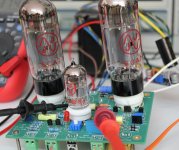
Looking at the pictures of your build I am wondering if the transistor emiters and collectors are reversed.
The Fairchild BC547B's I purchased from Mouser have a different pin-out from the 2N5551 noted as obsolete by many manufactures. The fairchild units I purchased, if mounted on the silk screen side of the board, must be soldered in place backwards. Check the data sheet for the transistors you are dealing with and compare it to the 2N5551 data sheet.
Papavienneau
Hi Jorge
Looking at the pictures of your build I am wondering if the transistor emiters and collectors are reversed.
The Fairchild BC547B's I purchased from Mouser have a different pin-out from the 2N5551 noted as obsolete by many manufactures. The fairchild units I purchased, if mounted on the silk screen side of the board, must be soldered in place backwards. Check the data sheet for the transistors you are dealing with and compare it to the 2N5551 data sheet.
Papavienneau
Jorge
Check pin-out of your transistors. The Silk-Screen on pcb's is for 2N5551 which are noted as "obsolete" on Mouser . The Fairchild BC547B's I purchase from Mouser, as recommended on the BOM, have their emiter and collector reversed. I therefore mounted my transistors backwards compared to the Silk-Screen. LED's do not blink on my boards.
I guess another option would have been to mount my transistors on the bottom of the board per top Silk-Screen orientation.
Papavienneau
Papavienneau is right thanks for the remark !
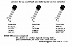
The pinout of transistors is different if they come from Europe, USA or Japan ! This is really stupid for a component with three pins they found a way to make three different pinout, may be for protectionism reason ?
Anyway, this could be the reason of your problem if you are using BCxxx transistors, see the attached chart...
Regards,
Marc
thanks for the remark !The pinout of transistors is different if they come from Europe, USA or Japan ! This is really stupid for a component with three pins they found a way to make three different pinout, may be for protectionism reason ?
Anyway, this could be the reason of your problem if you are using BCxxx transistors, see the attached chart...
Regards,
Marc
Attachments
I used the BC547B
Hi Marc and Papavienneau...!!!!
I feel that this is the problem. I used BC547B from Mouser and mounted as per silkscreen, as Marc says, it´s stupid to change the pinout being practically the same part, I also do not understand.
I have ordered a new batch of transistors from mouser (and some spare in case I mess desoldering and soldering), including the two big ones to be on the safe side as I do not know if those are broken due to the incorrect installation of the BC547B. Already sent from Mouser.
Does this amp benefit of being the BC547B transistors matched?
I will follow up as soon as I receive the package and install the new transistors.
Regards,
Jorge
Warning : do not use BC547B
Hi Jorge,
There is no need to match transistors for current source, but there is an other more critical point, the 2N5551 was specified because of its high Vce of 160 V and the BC547B is only 45 V which is not enough for this application, I don't know why I put this in the BOM Manufacturer code since I indicated the 2N5551 in the value, I was a little bit tired when I sent the 120 PCB's
I would recommend to stay with the 2N5551, it is still available in volume at Farnell : http://fr.farnell.com/on-semiconduc...MIkfmRw-Sx2gIVEd0bCh3OvwDxEAMYAyAAEgJp7vD_BwE
I would even suggest to buy a certain quantity since it is a very convenient transistor for tubes amplifier (I have bought 250 of them...).
I will check and correct the BOM ASAP
Sorry for that and happy that we found the problem !
Cheers,
Marc
- Home
- Amplifiers
- Tubes / Valves
- EL84 Amp - Baby Huey