Yes it is modular. Here are some pics of the PCBs. First the channel module (mic pre, EQ and routing):That's quite a nice build, right there! Is it actually modular or does it just look that way?
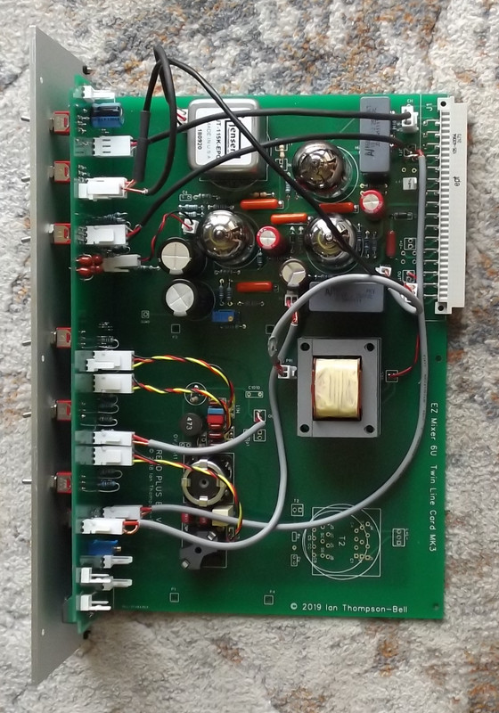
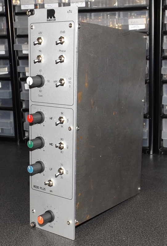
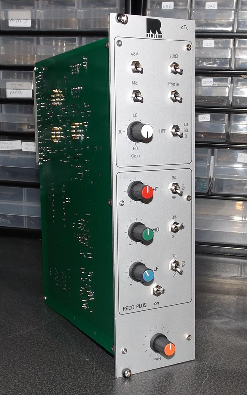
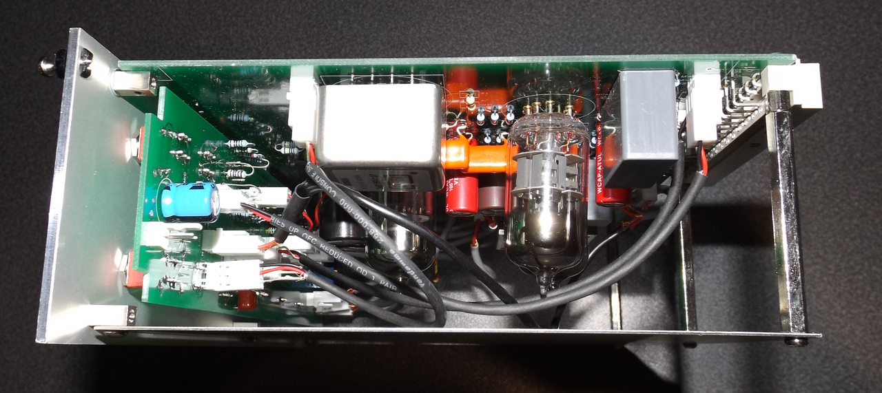
Then the channel module PCB as a completed module (several views)
The completed four channel module PCBs (there is room for 6 in the mixer)
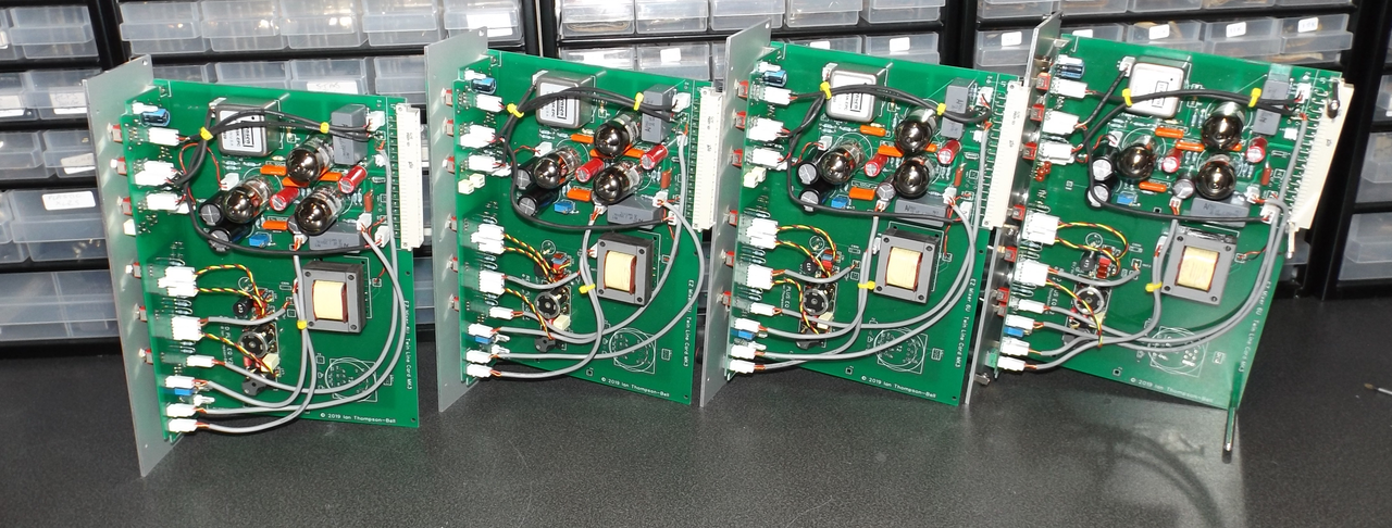
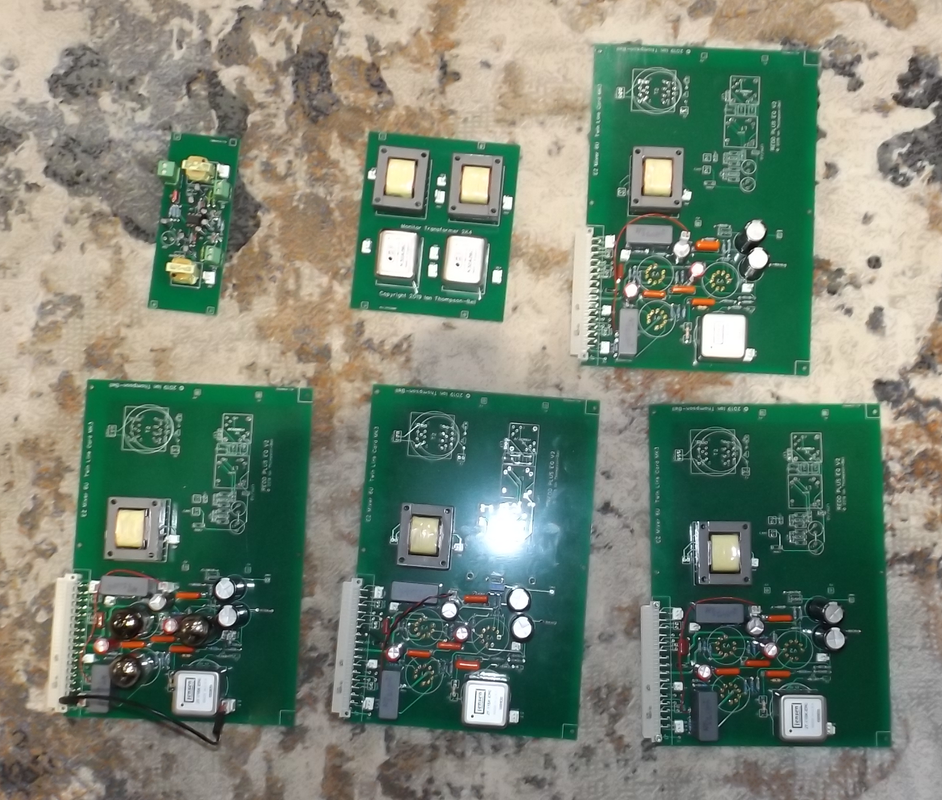
and lastly the complete set of PCBs for the mixer (channel amps, mix amp, VU buffer amp and monitor section transformer PCB)
Cheers
Ian
Congrats Ian is a BEAUTY !!!!!!! What are the advantages on use tubes rather then solid state component on mixers? ....all the best
Good question. When I worked at Neve back in the early 70s, all their designs were class A and their sound is revered today. Once ICs came along, everything changed to class B and the sound changed.
All my designs are class A so they have the same advantage in sound that the Neve designs of the 70s had. An added advantage is that they create less distortion than the equivalent transistor circuit so they need a lot less NFB
and their overload characteristic is much gentle. Add this to the fact they have enormous headroom due to a 250V supply rather than a 24V one and the answer is they sound simply sublime.
Cheers
Ian
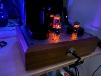
Beautiful workmanship! A lot of thought and design obviously went into the layout.Mind the fuzziness of the pictures. This is a 6p15p CCS loaded parafeed headamp I made for a buddy.
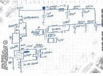
The schematic for interested parties. The parafeed capacitor will have to be tuned to the headphone impedance. Also it should be noted that the transformer may not be suitable for all headphones. A lower turns ratio may be in order for less sensitive cans than my AKGs.
Attachments
1pc 80x40mm Black Metal Shield Toroid Transformer Cover Protect Chassis Case | eBay
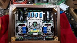
The chassis is a 2 level design to keep the top free of as many screws and bolts as possible.
The chassis is a 2 level design to keep the top free of as many screws and bolts as possible.
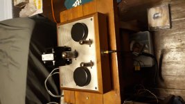
Line level Preamp and PSU for a Phono amp using the CCDA circuit as recommended by Coda and others.
PSU is 330 0 330v 60mA mains tmr, first cap 2 x 220u in series, 10H choke, then 820u 400v cap in parallel with two VR150/30's - HT 1 309v. HT two after 1k5 R and 50u cap each channel 288v.
Valves 2 x 6H8C. Tried LED as V1 bias, got better balance with resistor. All values the same - ish apart from 300r = 310r, 430r = 470r, I used what I had. Consequently each channel running at 14mA instead of 20mA, this is better for my mains tfmr too.
There's a few minor bits to do, like labels, EG PC, CD etc, better knobs and I have to find some screws.
well done from me ... very impressed
Andy.
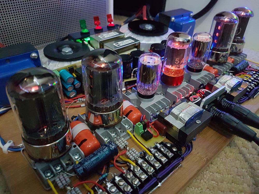
My collection: 833A power amp, 12ax7 preamp with 866A rectification and gas stabilisation and 307A poweramp with gas stabilisation.
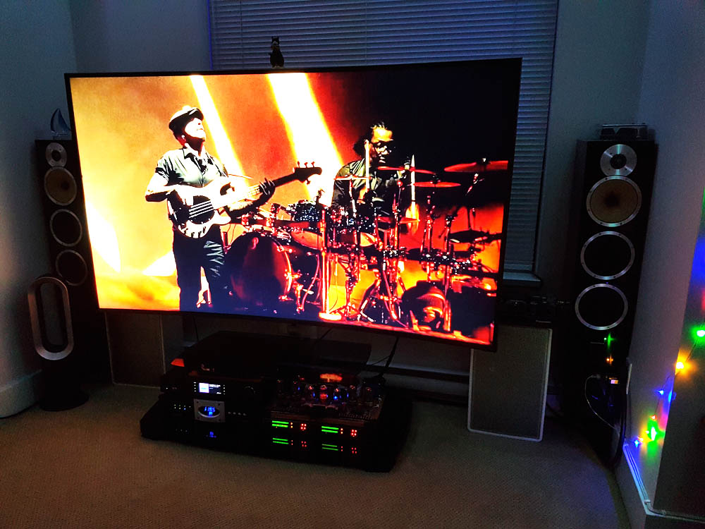
While it all looks very cramped, the chassis dissipate well and temperature-wise it is all within limits.
A lot of different lights when everything is "on".")
12ax7-e-307-A — imgbb.com
833-12ax7-307-A — imgbb.com
833-C-e-12ax7 — imgbb.com
2 — imgbb.com
4 — imgbb.com
While it all looks very cramped, the chassis dissipate well and temperature-wise it is all within limits.
A lot of different lights when everything is "on".
12ax7-e-307-A — imgbb.com
833-12ax7-307-A — imgbb.com
833-C-e-12ax7 — imgbb.com
2 — imgbb.com
4 — imgbb.com
Last edited:
I like the overkill of the 866A on the previous amp while there is a 833 next to it
I also have GMI-90 and GM100 in the basement! Now, that's overkill!
- Home
- Amplifiers
- Tubes / Valves
- Photo Gallery