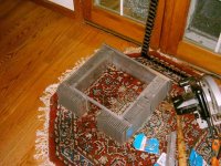
Sherman said:My first tube project. I'm sorry I built this, I can't stop now!
Is that one of those 11MS8 PP amps? (i think i've got the tube right -- a hard ome to remember)
dave
Hmm nice! is that a balanced horizontal mic socket as your B+?
How and Where did you find out that they are suitable for the task? if this is so...
Btw I love the woodwork and the fine display of old-style steel panelling with no chokes visible above!
Thanks!
Yep, thats a standard XLR male contact. They're rated for 250V AC. (this gives perhaps 250V*1,414 = 353V DC???)
I just tried one out, and no shorts have ever happened
") They are tested for no shorts at 1500V AC peak, so...
They are tested for no shorts at 1500V AC peak, so...I use the female contact for the part actually carrying the B+ voltage when the parts are not connected.
stigla.
Thanks for replying
If I go along with a seperate power supply chassis I think I'll be using a couple of em, don't know if they can handle 525-600volts DC at 100watts per side tho
We shall see...
Maybe i'll setup a simple voltage doubler with a few high-voltage paper in oil caps I have hanging around like 660volts AC aka 800 something DC... charge a few of em up on a voltage doubler and disconnect then let em rip
Btw, Kudos yet again on using that metal and panelling I love to see non-protruding screws in any valve equipment
Cheers..
planet10 said:
Is that one of those 11MS8 PP amps? (i think i've got the tube right -- a hard ome to remember)
dave
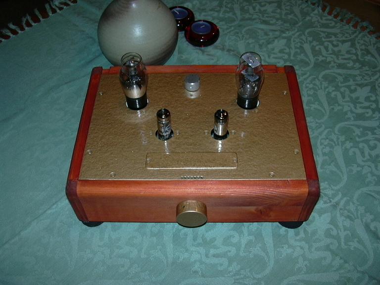
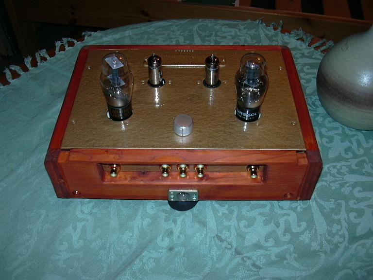
Yes it is (and yes it is, remembering that tube number I mean). I made changes only to accomodate the case (different volume pot, added the input selector (right hand knob), illuminated on/off switch instead of the stupid inline lamp switch that comes with it and a real fuse holder, again rather than the inline one that comes with it.
Other changes (but not to the real circuit) include filament snubbers and a cap across the HV. It sounds very good and has sufficient power to run my old Advent /1 speakers. (I've since built a pair of speakers so I'm not using the Advents with it anymore.)
I think that with the cost of the kit ~$150 US including shipping, a few caps, a rotary switch for the input selector, a set of RCA jacks for the inputs on the back, the knobs and the cool Padauk wood (that case has no stain at all, only three coats of clear poly) I probably have ~$200 US in it.

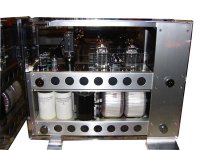
The 9 pin sockets are impatiently waiting for ECC83's. The rectifier is a 5U4G and the 2 empty holes will be for a future phono stage.What's with the 9 pin sockets?
I am following this schematic:
http://www.bonavolta.ch/hobby/en/audio/kt88_1.htm
I'm using Hammond 1627SE instead of the Tango U-808
I will write further comments about it at this thread:
power amp using kt88
Layberynthius Maximus, ¿have you finaly built this one?:
http://www.plitron.com/pages/Products/Audio/vtvkt88.htm
Layberynthius Maximus, ¿have you finaly built this one?: http://www.plitron.com/pages/Products/Audio/vtvkt88.htm
Nope ...
So far I have:
Audio-line caps
Preamp decoupling caps
no resistors
no power supply caps
no chassis
no valves
no trannies
duckload of coloured multi-strand steel wire, one sides rectifiers
And some 240 fabric-coated (authentic 1960's) power cord.
It's kind of hard kissing away a grand on transformers and half a grand on valves and 1/4 a grand on chassis metal and other misc stuff... when you live on $300 a month US$..
I'll keep you posted on how it sounds, however my designs and
months of planning may differ from anything anyone has built here
for good or bad
here is my latest amplifier - a direct coupled 45 stereo amp
Amperex 5842 gold pins driver, Cunningham CX-345 power triodes, Sylvania 5AR4.
Tamura F-475 output transformers and A-395 chokes.
An externally hosted image should be here but it was not working when we last tested it.
Amperex 5842 gold pins driver, Cunningham CX-345 power triodes, Sylvania 5AR4.
Tamura F-475 output transformers and A-395 chokes.
An externally hosted image should be here but it was not working when we last tested it.
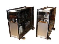
Here's a photo of the Glass Master SD-1.0, a mono tube power amp that we did around 1997~98.
The signal input goes into a 5814A which feeds a 6AH4GT voltage amplifier, followed by a 300B, which drives the 6C33C-B SEPP outputs. The power output measured about 30W.
In person, these are pretty big amps, measuring 180mm wide by 425mm high by 425mm deep, and tip the scales at 43kg each.
jonathan carr
Attachments
Wow!!
That's an incredible amp! I was going to build something similar to that but not as shiny ;D
^^With the power-amp tubes up-front for all to see with a vertical cabinet and the torodials down the back..
This is a very impressive and very cool set you made!
How would I get my hands on the design? I want to see if it
would be applicable to my selected amp.
Ahh yes I see there are two frames, one for PSU and another for actual amp/preamp...
With a plexiglass cover supporting the whole lot?
That's an incredible amp! I was going to build something similar to that but not as shiny ;D
^^With the power-amp tubes up-front for all to see with a vertical cabinet and the torodials down the back..
This is a very impressive and very cool set you made!
How would I get my hands on the design?
I want to see if itwould be applicable to my selected amp.
Ahh yes I see there are two frames, one for PSU and another for actual amp/preamp...
With a plexiglass cover supporting the whole lot?
833-amp
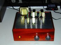
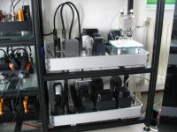
My contribution to this thread: my 833 poweramp.
Tubes: 6SN7 - 300B - 833. All transformer-coupled. The 300B in the picture is dwarved by the 833C next to it.
The amp consists of 2 parts: the amp itself and the external powersupply (the lower component in the picture).
Great sound and as a bonus you do not use your central heating anymore......
Reinout
Attachments
jcarr said:Here's a photo of the Glass Master SD-1.0, a mono tube power amp that we did around 1997~98.
Some day I'm going to have to build an amplifier that fits in a full-height drive bay. <Referring to your amps looking like computers> Something like stereo 6AQ5 SE ran at maybe 150% plate dissipation, with a fan to keep things cool (ratings, we don't need no steenkin' ratings), switching supply to convert 5 and/or 12V to HV and just run the heaters off 12V.
Tim
>That's an incredible amp!<
Thank you! But do bear in mind that the picture don't do these behemoths justice. We were the Nagra distributor around the same time, and so we did some audio shows with both the Nagra VPA and the Glassmaster on display. The VPA is a cute-looking design, but at the shows it was the Glassmaster that grabbed all of the oohs and ahhs.
>Ahh yes I see there are two frames, one for PSU and another for actual amp/preamp...<
Here's a side view so that you can see the stacked internal construction (front panel is at the left of the photo). As you surmised, the "ground floor" houses the power supply, and the "upper floor" contains the amplification section. The chassis is constructed mostly of stainless steel (suitably formed and machined), while the side panels are tempered glass, and have been left in place for this photo.
jonathan carr
Attachments
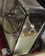
>With a plexiglass cover supporting the whole lot?<
No, the only use of plexiglass is for the upper section of the front panel (due to the corner curvature) and the illuminated power button (the rectangular piece that you see at the bottom of the photo). Behind the power button sits a bank of blue LED power indicators, and these shine into the power button (gloss-finished) via a frosted prism which diffuses the light into a soft glow. The lighting effect is much like a gentler version of the Hovland Radius power amp.
jonathan carr
Attachments
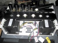
Current Status of 6 channel hybrid amp chassis
Attached is a photo of the chassis, such as it currently is, for my current amp project, the 6 channel hybrid HT amplifier. I just got finished cutting the major pieces except the top & bottom plates and back panel. I still have quite a bit of drilling and tapping to do - only gravity and friction are holding the pieces in the photograph together. Then I plan to have it black anodized and install the fun parts.
I have also prototyped the power supply so far, and will temporarily transfer it to a 'breadboard' on which I'll also prototype and test a single amplifier channel before assembling the six channels (each will mount to one of the individually removable heatsink sections which are seen in the photo). I expect roughly 6 x 150 wrms a channel into 8 ohms using a compactron tube for input & driver per channel & power mosfet outputs.
Attachments
- Home
- Amplifiers
- Tubes / Valves
- Photo Gallery