 ) - please - make new FE for it ; and SS rectifiers , with brute force PSU
- please - make new FE for it ; and SS rectifiers , with brute force PSU
output stage is elegant , so it should stay ....
FE? What do you suggest?
/Staffan
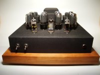
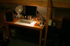
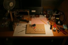
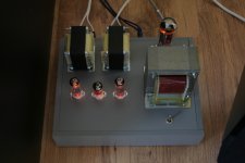
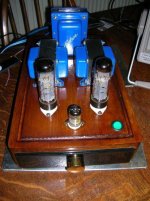
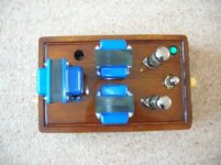
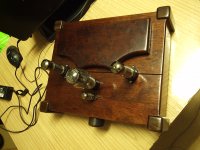
Here is my amp. It's made from 2 salvaged and modified Magnavox AMP142/132s.
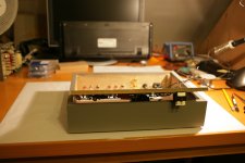
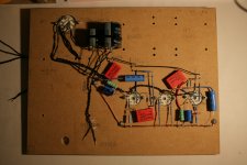
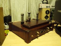
6CG7signal and paraphase inverter, 6V6 parallel push-pull, SS rectifier, 6HY PS choke, 1.5HY screen choke, 325 B+, 0.22uF couplers.
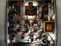
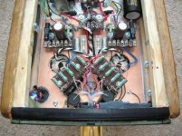
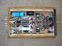
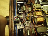
I removed some of the power caps you see in the picture. I also have it Triode strapped now, so I'm no longer using the screen choke and cap. I set them aside if I ever switch back to pentode mode.
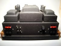
I also removed those adhesive tie-downs, they slowly "slide" down/around over time with heat. I now have the caps secured mechanically.
I still have a few things I want to do, like individual cathode resistors, stick a LED in the vintage pilot light, maybe a cathode follower in the front end etc.
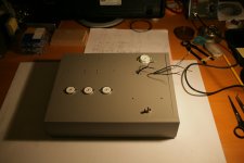
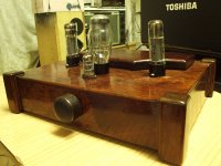
The "chassis", switches, IEC plug resistors and capacitors are new, the rest of the hardware was recycled. Even the fruitwood is from the original Magnavox console.
If there was a $200 buck amp challenge, this would be my entry.
I would take no less then $800 for it and would ask for a little more if I was to ever sell it.
Having said that I would put it up against any expensive tube amp of similar topology.
It is indeed a "sleeper", it's loud and hauntingly vivid sounding.
So any HKs or Marantz etc want a show down, it will be for pink slips.")
It's been a fun project, and I would highly recommend it.
Thank you for your time.
6CG7signal and paraphase inverter, 6V6 parallel push-pull, SS rectifier, 6HY PS choke, 1.5HY screen choke, 325 B+, 0.22uF couplers.
I removed some of the power caps you see in the picture. I also have it Triode strapped now, so I'm no longer using the screen choke and cap. I set them aside if I ever switch back to pentode mode.
I also removed those adhesive tie-downs, they slowly "slide" down/around over time with heat. I now have the caps secured mechanically.
I still have a few things I want to do, like individual cathode resistors, stick a LED in the vintage pilot light, maybe a cathode follower in the front end etc.
The "chassis", switches, IEC plug resistors and capacitors are new, the rest of the hardware was recycled. Even the fruitwood is from the original Magnavox console.
If there was a $200 buck amp challenge, this would be my entry.
I would take no less then $800 for it and would ask for a little more if I was to ever sell it.
Having said that I would put it up against any expensive tube amp of similar topology.
It is indeed a "sleeper", it's loud and hauntingly vivid sounding.
So any HKs or Marantz etc want a show down, it will be for pink slips.
It's been a fun project, and I would highly recommend it.
Thank you for your time.
Attachments
Here is my amp. It's made from 2 salvaged and modified Magnavox AMP142/132s.
6CG7signal and paraphase inverter, 6V6 parallel push-pull, SS rectifier, 6HY PS choke, 1.5HY screen choke, 325 B+, 0.22uF couplers.
I removed some of the power caps you see in the picture. I also have it Triode strapped now, so I'm no longer using the screen choke and cap. I set them aside if I ever switch back to pentode mode.
I also removed those adhesive tie-downs, they slowly "slide" down/around over time with heat. I now have the caps secured mechanically.
I still have a few things I want to do, like individual cathode resistors, stick a LED in the vintage pilot light, maybe a cathode follower in the front end etc.
The "chassis", switches, IEC plug resistors and capacitors are new, the rest of the hardware was recycled. Even the fruitwood is from the original Magnavox console.
If there was a $200 buck amp challenge, this would be my entry.
I would take no less then $800 for it and would ask for a little more if I was to ever sell it.
Having said that I would put it up against any expensive tube amp of similar topology.
It is indeed a "sleeper", it's loud and hauntingly vivid sounding.
So any HKs or Marantz etc want a show down, it will be for pink slips.
It's been a fun project, and I would highly recommend it.
Thank you for your time.
Very nice...
I know what you mean recycling parts...I built a fender champ from recycled parts..It feels good..
Also I don't think you can get the same sound with modern parts OP Tx's and such just have a sound all of their own..(The smell helps as well)..LOL
Regards
M. Gregg
Very nice work. Always nice to keep those vintage parts working too. How much of what is sold today will still be going strong in 50 to 60 years?
Probably nothing ... :-(
My first real DIY build, from RH84 schematic
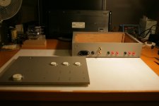
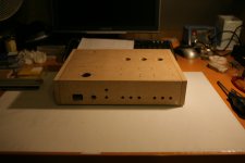
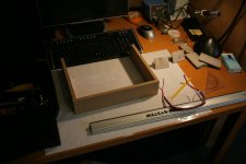
Build this amplifier last week! The dimensions of many pre fabricated cabinets are not of my liking, so I decided to build one myself.
It's a stereo single ended EL84 design using 'schade feedback'. It's build exactly according to Aleksandar Kitic's RH84 schematic.
It uses a JJ 5U4GB rectifier and a JJ ECC81 as driver. The power transformer is wound to my specification by 'AE Europe' in Schagen, Holland.
Output transformers (AT06) are from HB Amp Design in Germany. The parts are all ordered,
except the EL84's (Haltron, made by Tungsram factory) I had those lying around... mostly the reason I build this.
It sounds great! The lower frequencies are represented very well, and the mids and highs are very detailed, great schematic.
Attachments
-
 26_vr13jan.jpg929 KB · Views: 485
 -
 25_wo11jan.jpg653.5 KB · Views: 380
 -
 19_di10jan.jpg735.6 KB · Views: 383
 -
 18_di10jan.jpg869.7 KB · Views: 385
 -
 16_di10jan.JPG633.9 KB · Views: 333
 -
 15_ma09jan.jpg655.9 KB · Views: 319
 -
 11_ma09jan.jpg593.6 KB · Views: 399
 -
 06_za07jan.jpg600 KB · Views: 1,243
 -
 02_vr06jan.jpg641.4 KB · Views: 1,447
 -
 28_vr13jan.jpg592 KB · Views: 662
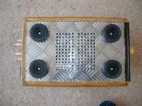
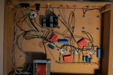
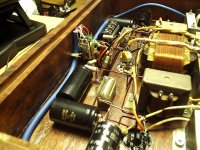
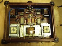
Its RFI shielding,
Covered in Foil..The caps are Mundorf silver in oil..Audio note pot..
I shielded The Tx's from the circuits..you can see the tape in the pic..
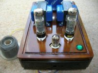
The finish was a moment of madness..shellac resin..
While I think about it notice no holes around the tubes...
The bases are gapped 3mm and mounted on silicone washers..
The vent at the back is driven by the heat of the choke..
Regards
M. Gregg
Covered in Foil..The caps are Mundorf silver in oil..Audio note pot..
I shielded The Tx's from the circuits..you can see the tape in the pic..
The finish was a moment of madness..shellac resin..
While I think about it notice no holes around the tubes...
The bases are gapped 3mm and mounted on silicone washers..
The vent at the back is driven by the heat of the choke..
Regards
M. Gregg
Attachments
Last edited:
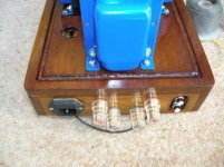
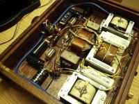
Looks good!, Is that a copper shielding in there?
Yes sorry just realised what you were looking at,
Across the front section for the tubes is a copper shield..(double sided PCB)
It seems to work well..
I can't tell when it's switched on except for the neon in the power switch its Dead silent, ear inside the speaker no hiss or hum like the speakers are disconnected..
Regards
M. Gregg
Last edited:
Well I notice,
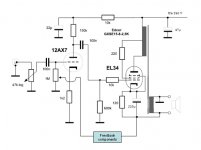
The schematic is missing in the Build thread..
So here it is...The line with feedback is not used it was just an Idea for global feedback and yes it does work, however just use a standard 1M ohm..
I use a dual log 100k In the volume position..
Thread is
http://www.diyaudio.com/forums/tubes-valves/179200-any-thoughts-circuit-3.html
Lots of design and help from artosalo and toprepairman (many thanks for a great project)
Regards
M. Gregg
Attachments
Last edited:
I would refuse the capacitor at the input
There are lots of tweeks this is just the schematic as was..because it has gone missing in the build thread..
And no global feedback is used...I like the sound...its close in schematic to a PYE mozart...
Please note that the secondary is providing the feedback..and needs the earth..
If you get the secondary out of phase it will be unstable..
If you remove the box saying feedback components and the lines so you just have a standard 1M resistor with secondary in the cathode + Gnd thats it..
Without the 220 you will get grid current..
Regards
M. Gregg
Last edited:
Also if no GNFB drop the earth from the secondary of the OPT. Let the secondary float.
How can I do that when its carrying the cathode current?
Yes its strange..
Regards
M. Gregg
E88CC + EL34 SE, 5,5W @ 8 Ohm
Attachments
- Home
- Amplifiers
- Tubes / Valves
- Photo Gallery