My attempt at an Aikido
I think it looks OK. My wife reckons that I should stain the pine a darker color? However, the camera has picked out scratches.
I am using diode rectified power. The rear tube is an Amperite 30 second delay. I have a separate 6.3VAC heater transformer, which is rectified and regulated using a Welborne Labs kit.
At some point, I'll upgrade to 12VDC and expermiment with 12V tubes.
Charlie
My First EL84 PP
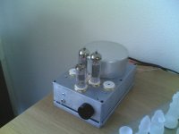
This my very first self built Tube Amp (actually I have built two of these since they are monoblocks)
It is based on a design in Radio Electronica from 1962
I replaced the power and output transformer by a set of Amplimo toroids (one inside the case and the other outside, stacked on a single M6 thread)
The tubes are 2 x EL84(of course) and an ECF83 as input stage and phase splitter.
All built into a Hammond cast aluminium box (quite small... I had to use some surgical handyness to get it all in...) the box runs quite hot though when it runs for a few hours :-( No chance i can close it up the way it was meant to be") (that's why its floating above the lid)
(that's why its floating above the lid)
I planned to put 4 EL84 on the box since the output transformer is only 4 k anode-anode but the amplifier gets unstable with 4 tubes. Might be that the power transformer can't keep up but all voltages read quite OK. I also had a problem with the ECF83 generating some HF oscillation when driven with a large signal. For now I blocked it with a (too large) styroflex cap of 200 pf between anode and kathode.
This my very first self built Tube Amp (actually I have built two of these since they are monoblocks)
It is based on a design in Radio Electronica from 1962
I replaced the power and output transformer by a set of Amplimo toroids (one inside the case and the other outside, stacked on a single M6 thread)
The tubes are 2 x EL84(of course) and an ECF83 as input stage and phase splitter.
All built into a Hammond cast aluminium box (quite small... I had to use some surgical handyness to get it all in...) the box runs quite hot though when it runs for a few hours :-( No chance i can close it up the way it was meant to be
(that's why its floating above the lid)I planned to put 4 EL84 on the box since the output transformer is only 4 k anode-anode but the amplifier gets unstable with 4 tubes. Might be that the power transformer can't keep up but all voltages read quite OK. I also had a problem with the ECF83 generating some HF oscillation when driven with a large signal. For now I blocked it with a (too large) styroflex cap of 200 pf between anode and kathode.
Attachments
Hi all,
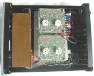
This is my most recent work: a trivial ultralinear amp, 60WRMS/channel.
Input tubes 6922 and power tubes 6550C (or KT88), continuously variable neg. feedback on front panel knob, overkill (almost...) output stage power suplly, independent input tubes power supply (cap/choke/cap), also separated for bias and for the input stage DC heaters.
3 steps manual power on sequence and HT standby switch.
Fixed bias and 0, 4 and 8 ohms speaker taps
All aluminum chassis and piano black hand buffed front panel.
Sounds very very natural and cristal clear.
[ ]s
Ricardo
An externally hosted image should be here but it was not working when we last tested it.
An externally hosted image should be here but it was not working when we last tested it.
An externally hosted image should be here but it was not working when we last tested it.
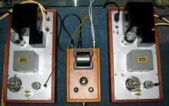
rcavictim said:Nice job RW. I like the clean wiring inside.
Looks like you can check the output tube bias current from the top but you need to go inside to adjust it.
Hi rca,
Thanks for your kind words.
No it is not that way: you can also reach the pots for bias adjustments from the top, they are (each one) just behind the bigger tubes but unfortunately the previous pics could not show them at all...
[ ]
Ricardo
An externally hosted image should be here but it was not working when we last tested it.
An externally hosted image should be here but it was not working when we last tested it.
I did not know it was possible to do such a beautiful job of point to point. I take it that those bus bars are lacquer coated transformer wire? .... Do you coat the inside of the chassis with this as well?
Also looks like plastic caps through out, except for those quality electro's on the power lines ...
Very neat, very tidy, better than factory work, a sight better than anything I have ever been able to do ...
Also looks like plastic caps through out, except for those quality electro's on the power lines ...
Very neat, very tidy, better than factory work, a sight better than anything I have ever been able to do ...
FastEddy said:I did not know it was possible to do such a beautiful job of point to point. I take it that those bus bars are lacquer coated transformer wire? .... Do you coat the inside of the chassis with this as well?
Also looks like plastic caps through out, except for those quality electro's on the power lines ...
Very neat, very tidy, better than factory work, a sight better than anything I have ever been able to do ...
Thank you all guys.
FastEddy:
Yes those bars are coated transformer wire and are excellent in these applications.
I don't coat the chassis inside.
Those are really nice caps but without the sky high price for audiophile quality...
It's more difficult to previously think about the routes of all those wires than doing the job itself.
Try it: you will then develop your own way of doing that and the results are fantastic.
[ ]
Ricardo
FastEddy said:Thanks for the tips, but I don't believe I could do as giood a job without lots of practice ... Can we see pictures of you other DIY projects? (I'm sure you have more.)
Hi Fast,
I've already some other pictures shown here (you have to search a little...)
Meanwhile see this line preamp: 15 dB gain and using 12BH7/12BH7/12AT7, pi choke filtered and stabilized power supply, big power trafo and some audiophile touchs like Solen caps and a BBeauty Alps pot.
You are right: it is not impossible to do that kind of wiring BUT you have to have chinese patience...
[ ]
Ricardo
An externally hosted image should be here but it was not working when we last tested it.
An externally hosted image should be here but it was not working when we last tested it.
An externally hosted image should be here but it was not working when we last tested it.
An externally hosted image should be here but it was not working when we last tested it.
Giaime said:I have a question for rwellerson: I see you use PCBs with some kind of "ground plane" on top. But... how you get to have that beautiful "metallization" of the copper ground plane? That's very shiny, did you use a solder bath or what else?
Extremely good work, indeed
Hi Giaime,
Thanks!
Yep that is a ground plane and I do it this way: I melt common solder (63/37 works better) on the entire surface with a strong solder iron (60W, unfortunately no bath....) and get a uneven finish at first.
After this I use a small gas flame (a "far east" minitorch gas lighter works wonders....) to level out the small bumps and then use some fine texture steel wool with water and soap to polish the surface.
To avoid accidental shorts when probing the top components I also use 2 coats of clear acrylic automotive lacquer.
[ ]
Ricardo
An externally hosted image should be here but it was not working when we last tested it.
An externally hosted image should be here but it was not working when we last tested it.
- Home
- Amplifiers
- Tubes / Valves
- Photo Gallery