Very nice! It's screaming for some bling transformer covers..
Thank you.
Yes, but they would have to be custom made, the spacing doesn't allow for anything "standard."
Maybe just spray paint the transformers a nice metal color?
Last edited:
Very nice! It's screaming for some bling transformer covers..
bloddy expencive
probably half the budget

but ofcourse there are ways to solve that
nice work

You could cut a disk out of wood to fit the inside of the pipe. If you dont like the wood look use some bondo to fill in the grain and paint the enclosure.Just what popped up in my head: a few pieces of pipe, painted accordingly. The top you'll have to figure out yourself
Spray paint the transformers?
I'm actually taking a break now from transformer (cover) painting (a learning process) and it has taken long enough..
What metal is the top plate, and is it polished?
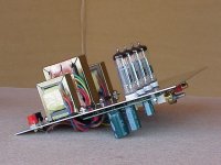
It is a sheet of aluminum, yes I had to polish it. I cut the aluminum to size on a table saw. they have blades that can do that. I then drilled all the holes. The 4 tube socket holes were drilled with a spade wood bit, I had to modify the bit so that it would cut through aluminum. When I was finished cutting, drilling and filing, I polished it by hand. Wet or Dry sandpaper, ultra fine grade steel wool and SIMICHROME polish!
I agree with most: Nice job on the top panel!! I wonder if it has a clear acrylic spray finish or if it's raw aluminum?
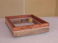
The rabbeted / mitered base is my preferred construction method, too- I routed out a little wider, then used brass inserts in the walnut to accommodate oval head machine screws in the top panel.
How do you secure your top panel to the base? I can't quite see, from the pix... Nice job!!!
The base turned out really fine, too- I like the bubinga/walnut combination!
Would never of thought of it but a good idea.
Any noise from the leds. They are meant to be noisy little devils.
Do we have postable schematic. I did a 12AX7/6AS7 SET. Just two tubes and rec tube. Love the amp-3W. Every one who listens to it wants one.
Here's the sloppy MS visio schem:
An externally hosted image should be here but it was not working when we last tested it.
Uploaded with ImageShack.us
Honestly, I notice that LED's tend to be quieter than a fat electrolytic sopping up noise into its big metal can
This thing is dead silent, much better than resistor/cap combo. This LED sits at about 1.7v, and I can't detect any AC across it with my DMM, music going or not.
Thank you.
It's not secured, just a snug fit, a little bit of friction holds it in place. If I were to flip the amplifier upside down, the plate would probably fall out. But why would I do that?
No clear spray on the aluminum, I thought about it, but if I scratched the finish during assembly, I'd have to respray the top all over again. As long as you keep your fingers off the aluminum, it stays shiny.
I agree with most: Nice job on the top panel!! I wonder if it has a clear acrylic spray finish or if it's raw aluminum?
The rabbeted / mitered base is my preferred construction method, too- I routed out a little wider, then used brass inserts in the walnut to accommodate oval head machine screws in the top panel.
How do you secure your top panel to the base? I can't quite see, from the pix... Nice job!!!
The base turned out really fine, too- I like the bubinga/walnut combination!
Let's say you did you a 2V LED. What woul be the effect?1.7v red LED from an assortment I've had for a while, most reds are 2v~ or so nowadays, so you should dig through a pile of older ones to hand pick the best for your purpose.
The current through the tube would go down, which would cause there to be less drop across the plate resistor. Increase the plate resistor slightly (maybe try 120k/150k), you want about 1/2 the B+ across the first triode, I've gotten the best swing at 150v plate with around 1.7v bias.
Last edited:
Is that a good general rule of thumb: half B+ across the triode??The current through the tube would go down, which would cause there to be less drop across the plate resistor. Increase the plate resistor slightly (maybe try 120k/150k), you want about 1/2 the B+ across the first triode, I've gotten the best swing at 150v plate with around 1.7v bias.
Can you think of a negative for using a LED? Is there ANY down side???
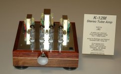
I'm thinking on building the same amp. i have most of the parts but i need to decide if 3w is enought. Is it possible to have a switch to go from triode to pentode without changing the rest of the design..(to much)My latest creation. Class A, 3W per channel, single ended. Can be easily changed to pentode mode. I made this one for sale, but still not sold
An externally hosted image should be here but it was not working when we last tested it.
An externally hosted image should be here but it was not working when we last tested it.
An externally hosted image should be here but it was not working when we last tested it.
1.7v red LED from an assortment I've had for a while, most reds are 2v~ or so nowadays, so you should dig through a pile of older ones to hand pick the best for your purpose.
LEDs can run many voltages. I've seen red LEDs that run 1.7 volts and ones that run 2.4 volts, it's an aspect of the manufacturers design. While it's interesting that you biased your amp with one it doesn't reduce the 'noise' of a capacitor that acts like a short in a cathode circuit.
Also what happens with diodes and LEDs is that the insertion loss (voltage drop) is not a constant. That is at one current the drop is not the same as it is at a higher or lower current, although at the low current running through the 12SN7 is pretty low so the drop shouldn't vary much. You could use a silicon diode for example (1N4001) that has a .7 volt forward drop and string them to give you the desired grid voltage you want but it's easier, and more accurate, to do with a resistor (metal film) and a capacitor. A 100uF/6V capacitor isn't much bigger than your LED.
Rob
Is that a good general rule of thumb: half B+ across the triode??
Can you think of a negative for using a LED? Is there ANY down side???
More or less, thats just a good general rule of thumb. It just really depends on the B+ and tube you choose, some designs you can get away with 1/4 ~ 1/3, but I like to go for 1/2 B+.
LEDs can run many voltages. I've seen red LEDs that run 1.7 volts and ones that run 2.4 volts, it's an aspect of the manufacturers design. While it's interesting that you biased your amp with one it doesn't reduce the 'noise' of a capacitor that acts like a short in a cathode circuit.
Also what happens with diodes and LEDs is that the insertion loss (voltage drop) is not a constant. That is at one current the drop is not the same as it is at a higher or lower current, although at the low current running through the 12SN7 is pretty low so the drop shouldn't vary much. You could use a silicon diode for example (1N4001) that has a .7 volt forward drop and string them to give you the desired grid voltage you want but it's easier, and more accurate, to do with a resistor (metal film) and a capacitor. A 100uF/6V capacitor isn't much bigger than your LED.
Rob
Pretty much what he said. They're good for relatively constant current swings, or for things like constant voltage sinks (less drop than a resistor at the same current swings by far) under output tubes. You really should get some samples and test for good impedance characteristics. Sy has good write up and discussions in various threads on here, definitely check up on his projects, theres a lot to learn.
- Home
- Amplifiers
- Tubes / Valves
- Photo Gallery