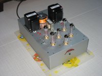
S5 K-16LS kit project that I just finished. First time with tubes so I figured I'd start with a kit so I can learn without killing myself in the process.
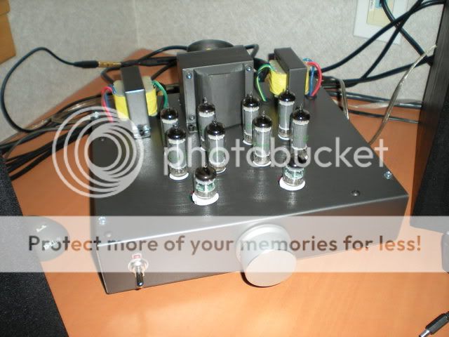
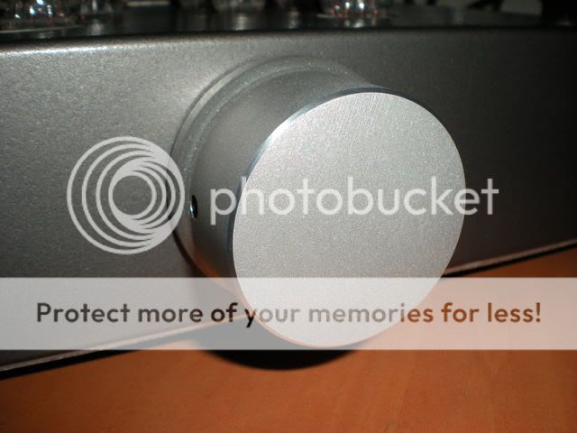
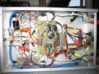
From scratch from 1mm aluminium sheet, I custom made the knob on my school's lathe and made some covers for the power transformer to make it looks more snappy.
Matching input/output selection box in the works.
From scratch from 1mm aluminium sheet, I custom made the knob on my school's lathe and made some covers for the power transformer to make it looks more snappy.
Matching input/output selection box in the works.
1st build
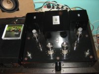
This is my first scratch build. 1626 Darling with a LCLCLC PS and 5V4G rectifier. Had to use a bucking trafo to bring the voltages down as my mains has been running 125-126V.
This is my first scratch build. 1626 Darling with a LCLCLC PS and 5V4G rectifier. Had to use a bucking trafo to bring the voltages down as my mains has been running 125-126V.
An externally hosted image should be here but it was not working when we last tested it.
An externally hosted image should be here but it was not working when we last tested it.
An externally hosted image should be here but it was not working when we last tested it.
An externally hosted image should be here but it was not working when we last tested it.
Just finish my dynaco st-35 clone with 2 el-84s in PP per channel. The poor power transformer gives only 300V for the B+ with bias around 30mA per tube. Don't know the output power, can any one offer some hints. The OPT is Hammond 1620 with 6600 ohm per primary. Some crackling noise on one channel, may be the socket or the tube problem.
Attachments
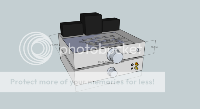
Some pics of a small amp to be. It is a 6AQ5-SE on a 100 x 110mm alu-plate. The final measurements till be slightly bigger as I really cannot fit the three PSU caps in the space.
Transformers are 5K SE-trannies from Analog-Metric and power tranny is a R-core from vt4c.com.
Transformers are 5K SE-trannies from Analog-Metric and power tranny is a R-core from vt4c.com.
An externally hosted image should be here but it was not working when we last tested it.
An externally hosted image should be here but it was not working when we last tested it.
Soundbrigade Q&A:
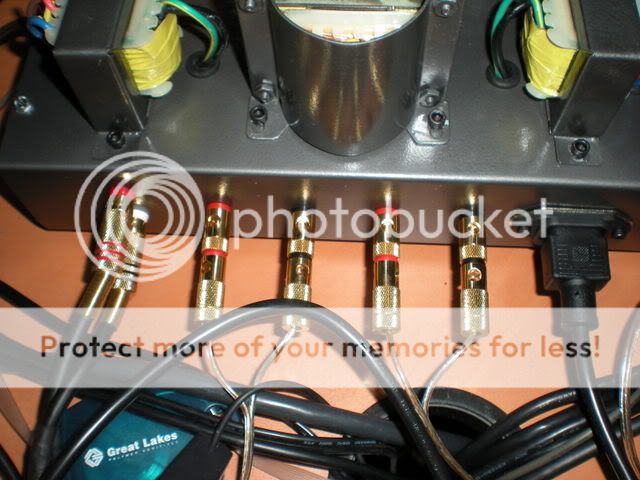
When you install the tranny, how do you parallel the primaries for 115 VAC? Red to Green and Yellow to Orange ?? (I get it about 230 VAC ... Green spliced to Yellow, right?) (I had some difficulties with a German transformer a while back, the colors were in German on the label and I had to Babelfish the US gringo wire colors to get a translation ... and still messed up. )
)
When you install the tranny, how do you parallel the primaries for 115 VAC? Red to Green and Yellow to Orange ?? (I get it about 230 VAC ... Green spliced to Yellow, right?) (I had some difficulties with a German transformer a while back, the colors were in German on the label and I had to Babelfish the US gringo wire colors to get a translation ... and still messed up.
)Answer:
I think, hope, pray and guess that the tranny is wired as indicated on the sticker. In this case for 230V I connect RED and ORG to line and connect YEL and GRN together.
Had I wired it for 115V, I had wired ORG and YEL together and GRN and RED together.
The latter may be the case as we will go to the States in June and I may (or may not) have reason to bring the amp and show it to some people as an example of miniature Swedish artmanship ...
If I had installed the mains transformer 1/2" to the left (or right) there would have been some space for the caps ...
This is great fun - on restricted budget or restricted space try to build something that is working OK. I don't admire people that builds 5-ton amps spending some 1000$ on tubes or transformers.
Less is more.
This is great fun - on restricted budget or restricted space try to build something that is working OK. I don't admire people that builds 5-ton amps spending some 1000$ on tubes or transformers.
Less is more.


" ... when the color is not in English. Same when someone from Quebec honks their car horn and it is in French! ..."
I got that already. There is a disconnect with wire color codes on US equipment, etc., verses the Euro "standards". FYI: DC color code for a black wire would be a ground wire, right? Then what is all that stuff in my walls that is hot enough to burn briskets?
I got that already. There is a disconnect with wire color codes on US equipment, etc., verses the Euro "standards". FYI: DC color code for a black wire would be a ground wire, right? Then what is all that stuff in my walls that is hot enough to burn briskets?
" ... green or green/yellow is for ground ..." ... In Europe, but I've seen it a lot here in the last decade or so. (Oops: http://en.wikipedia.org/wiki/TRS_connector#Color_Codes ... Oops again: http://en.wikipedia.org/wiki/Electrical_wiring#Colour_code )
I've always preferred the older codes = "black to brass" for single phase AC above 70.7 VAC (house wire codes & limits) ... and black and/or green for the VDC ground (up to higher voltages), leaving the colors for various VDC "hot" voltage levels, like red for V+ (VCC) and Blue or Yellow for V- (VDD) = like it is inside your basic clone computer.
I am sure someone somewhere has a "standard" for audio electronics that would help us all = got links?
: http://en.wikipedia.org/wiki/Tip_and_ring & http://en.wikipedia.org/wiki/25-pair_color_code = The TelCo / Telecom codes for 25 & 50 pair phone snakes. (Jeez, I have totally forgotten what I had to learn decades ago to be in the union as a telecom/commtech = " ... For cables with over 25 pairs, the first 25 pairs (called a binder group) are marked with mylar ribbons using the colors of the color code starting with a white/blue ribbon ..." ... and that's in North America, your country may vary! )
I've always preferred the older codes = "black to brass" for single phase AC above 70.7 VAC (house wire codes & limits) ... and black and/or green for the VDC ground (up to higher voltages), leaving the colors for various VDC "hot" voltage levels, like red for V+ (VCC) and Blue or Yellow for V- (VDD) = like it is inside your basic clone computer.
I am sure someone somewhere has a "standard" for audio electronics that would help us all = got links?
: http://en.wikipedia.org/wiki/Tip_and_ring & http://en.wikipedia.org/wiki/25-pair_color_code = The TelCo / Telecom codes for 25 & 50 pair phone snakes. (Jeez, I have totally forgotten what I had to learn decades ago to be in the union as a telecom/commtech = " ... For cables with over 25 pairs, the first 25 pairs (called a binder group) are marked with mylar ribbons using the colors of the color code starting with a white/blue ribbon ..." ... and that's in North America, your country may vary! )Re: 1st build
Beautiful work on your Darling. I've been using mine for about 4 years & have yet to find anything I like better. I'm working on a "super" Darling (waiting for OPTs from MagnaQuest) & would love to shoot the breeze with you, specially since we're both in the Lone Star State. Drop me a PM if interested.
bloozestringer said:This is my first scratch build. 1626 Darling with a LCLCLC PS and 5V4G rectifier. Had to use a bucking trafo to bring the voltages down as my mains has been running 125-126V.
Beautiful work on your Darling. I've been using mine for about 4 years & have yet to find anything I like better. I'm working on a "super" Darling (waiting for OPTs from MagnaQuest) & would love to shoot the breeze with you, specially since we're both in the Lone Star State. Drop me a PM if interested.
Hello yall from the diy Audio Board!
I hope you dont mind me showing my own diy project even if its not HiFi Audio (as I am still fairly proud of it ), my very own guitar amp head! I attached two pictures from the front and the back.
Front:
and Back:
Please forgive me the crappy picture quality, but I wanted to get ahold of the sweet glow.
In this prototype I designed the circuits myself. You might wonder why I have 8 power tubes? These are 4x 6L6GC and 4x EL34 which are switchable during play (the lever switch between the orange and the green led at the left in the front view).
3 independent channels with active EQ yabba yabba etc etc...
thanks and enjoy (hopefully as much as I do)!
I hope you dont mind me showing my own diy project even if its not HiFi Audio (as I am still fairly proud of it
), my very own guitar amp head! I attached two pictures from the front and the back.Front:
An externally hosted image should be here but it was not working when we last tested it.
and Back:
An externally hosted image should be here but it was not working when we last tested it.
Please forgive me the crappy picture quality, but I wanted to get ahold of the sweet glow
.In this prototype I designed the circuits myself. You might wonder why I have 8 power tubes? These are 4x 6L6GC and 4x EL34 which are switchable during play (the lever switch between the orange and the green led at the left in the front view).
3 independent channels with active EQ yabba yabba etc etc...
thanks and enjoy (hopefully as much as I do
)! That thing is bada$$
I hope you dont mind me showing my own diy project even if its not HiFi Audio
The tube amp forums aren't just for HiFi guys. It just seems like that because were the ones you see bickering the most.
So 6L6 vs. EL34, whats your impressions?
- Home
- Amplifiers
- Tubes / Valves
- Photo Gallery