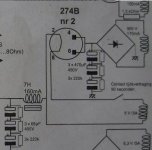
You have a nice soft start circuit. Here the tube is just used for its turn on capabilities. Once the amp starts instead of B+ being at full potential it comes up as per normal tube rectifer being used. From what i see ss allows very high first capacitance value where else the tube will only see max of 47uf. Also in this case the tube is parallel for most normal rectifer tubes and allows double the amount of current flow.
Hope this helps
Hope this helps
The first capacitor is connected BEFORE the vacuum diode, so it will have to be rated for peak of unloaded AC. Depending on warmup time, the output voltage won't rise nearly as high.
In this case, it would not reduce the switching noise. However, using its two diodes as half of the bridge WOULD reduce switching noise, as the SS and vacuum diodes are in series. But you'd be subject to the tube's peak current rating...
If I were building this circuit, I'd use the 6AU4 or 6DW4, not a WE tube made of unobtanium...
Just wierd to me........
As stated, use two damper rectifier tubes such as the 6DE4 in one-half of the bridge to enjoy a quiet rectifier & delayed warm up of 20 to 25 seconds.
Who would want to find a somewhat rare 1.5KV rated relay anyways plus the delay circuit electronics.
60uF is plenty of capacitance & the damper diodes can handle that. That large capacitance of over 150uF is overkill for such a light current load. Plus, a the large in-rush current without a soft-start circuit at start-up & very high peak to average current causes strain on the high-voltage transformer.
For more advanced technique on how to remove ringing from SS rectifiers, see here http://www.hagtech.com/pdf/snubber.pdf. Check especially page 10 and 11 for differences using single caps and more advanced snubber networks.
I use series resistor cap combinations for all rectifiers in my OTL's with good results but I needed to do a lot of measurements to get the values right, I also use soft fast recovery diodes.
Regards Hans
I use series resistor cap combinations for all rectifiers in my OTL's with good results but I needed to do a lot of measurements to get the values right, I also use soft fast recovery diodes.
Regards Hans
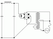
Graetz rectifier
.
AFAICT The performance is the same whatever type of SS diode is used. The reason is that the charging current is always in series with a thermionic diode.
So use the cheapest.
.
eeka chu said:Are these normal SS diodes or Schottky / Soft Recovery diodes?
AFAICT The performance is the same whatever type of SS diode is used. The reason is that the charging current is always in series with a thermionic diode.
So use the cheapest.
Re: Graetz rectifier
I mean for those using snubber networks, since Schottkys don't have a reverse recovery.
dhaen said:.
AFAICT The performance is the same whatever type of SS diode is used. The reason is that the charging current is always in series with a thermionic diode.
So use the cheapest.
I mean for those using snubber networks, since Schottkys don't have a reverse recovery.
I mean for those using snubber networks, since Schottkys don't have a reverse recovery.
If you talking about all SS bridges then I recommend to use soft recovery diodes as the ringing is much smaller even without snubbers but the same snubber dimensioning works also for normal diodes, (with different component values).
It is true that Shottky diodes by definition doesn't have reverse conduction in the normal sense but the capacitance of the package will normally give some reverse conduction and ringing.
Regards Hans
tubetvr said:
It is true that Shottky diodes by definition doesn't have reverse conduction in the normal sense but the capacitance of the package will normally give some reverse conduction and ringing.
Regards Hans
Is this the case in higher voltage rectifiers for tube amplifiers, or is this also the case in lower voltage ss amplifier rectifiers?
tubetvr said:
It is true that Shottky diodes by definition doesn't have reverse conduction in the normal sense but the capacitance of the package will normally give some reverse conduction and ringing.
Yep, of coarse theoretically the junction would have zero, but reality's never quite so kind.
")
Even a valve rectifier will have some degree of capacitance and reverse recovery, just a very small amount of it.
The best solution would be to use high quality rectifiers and a high quality snubber network to reduce the reverse recovery to an absolute minimum. But that always means time, space & $$$'s.
I think I'm trying to reason whether it's more effective to start out with higher quality diodes (Schottkys / Soft Recovery) and no network or to use lower quality diodes (Regular silicon) and add a network to correct the original mistakes; in other words, which is more effective for the time, space, money etc. Since most SS diodes are about the same size for a given rating, virtually regardless of their quality, the version with a snubber network will already be behind in terms of space.
Re: Graetz rectifier
In our case IN4007 + EZ81
Since the fix never quite cures the problem, best to not have to do the fix.
dave
dhaen said:So use the cheapest.
In our case IN4007 + EZ81
eeka chu said:I think I'm trying to reason whether it's more effective to start out with higher quality diodes (Schottkys / Soft Recovery) and no network or to use lower quality diodes (Regular silicon) and add a network to correct the original mistakes;
Since the fix never quite cures the problem, best to not have to do the fix.
dave
Yep, of coarse theoretically the junction would have zero, but reality's never quite so kind
A "real" Schottky diode where there is a pure metal to semiconductor region doesn't have any minority carriers and doesn't therefore have any reverse recover time except for what you get from the capacitance. Old Germanium diodes as 1N34 or 1N21 are actually schottky diodes and there are many modern ones in silicon or GaAs that is used for microwave detection and mixing
Normal Schottky diodes as the ones for rectifying higher currents are not "real" as they are made in a normal monolitic process and the interface between the metal and the semiconductor is not so pure and not so well defined, the result is some reverse conduction, (but much less than for PN junction diodes).
Even a valve rectifier will have some degree of capacitance and reverse recovery, just a very small amount of it.
There must be some reverse recovery from the capacitance but nothing from any other means AFAIK, I have never measured it but it would be interesting to see what the performance of a vacuum diode really is.
Regards Hans
- Status
- This old topic is closed. If you want to reopen this topic, contact a moderator using the "Report Post" button.
- Home
- Amplifiers
- Tubes / Valves
- hybrid rectifier question