Re: Hammond 1627 OPT
Thanks Johnny, I'll try it both ways as there seems to be some conflicting thought as to how to hook this OT up.
Yes, the OT's now have 3 taps on the output.
I'm actually adding a DP 3 position rotary switch to my build so I can select between all 3 if needed.
Glenn
kmtang said:I believe the Red wire goes to B+ and Blue wire goes to the plate. To make sure you get the best performance from the OPT, try connect it both ways and measure it's frequency response.
Johnny
kmtang said:I just noticed that Hammond's OPT has new configuration. The new version having all 4, 8, and 16 ohm tappings available. The oldere version either you can configured it to 4 and 8, or 16-0hm only.
Johnny
Thanks Johnny, I'll try it both ways as there seems to be some conflicting thought as to how to hook this OT up.
Yes, the OT's now have 3 taps on the output.
I'm actually adding a DP 3 position rotary switch to my build so I can select between all 3 if needed.
Glenn
porkchop61 said:...I have a question about the 6N1P.
I see it's anode current is rated anywhere between 5.6-10.5mA. ...
I should double that for a stereo version?...
I forgot to ask, what are you using for a schematic for the guitar amps? I think you said it was part of 2 different designs?
Please post pix when you get the chassis done. I'd be intersted in seeing them.
Glenn
Yep, I have only 1/2 the tube connected in my monoblocks, each triode would be at about 5mA so 10mA for both running.
My guitar project is sort of a combination of the AX84 P1 and P1 Extreme. I'm planning on using the EL84 output stage of the P1 and the preamp stages from the P1 Extreme.
The circuits are very similar but the P1 Extreme adds drive and master volume controls (the P1 has only volume). Both also have bass, mid and treble tone controls. The P1 Extreme's output stage is an EL34.
With the EL84 I'm hoping for about 5 watts in pentode and UL modes and maybe 2 in triode.
I'll post pics if it doesn't explode!

Yes, I love the master volume!
Of course it only preamp 12AX7 tube distortion. The output tubes add an extra level of distortion that sounds different.
I used the "High-Octane" preamp design on my McMartin MA-20 rebuild. A LOT of gain in the preamp section! This amp uses a PP 6L6 setup for the power amp. It only has a Baxandall type tone stack, but it's pretty good sounding after a few component changes.
Good luck with the build.
Back on the subject of the KT88 SET amp-
Does anyone here use soft start circuits in their power amps? I've seen transmitters that use a resistor in the circuit for startup, and then switch it out after with a relay. I think this is more than I would like to tackle. I was thinking of using a thermistor for a soft start. I know they get quite hot when running, but they should work well. Has anyone tried these in a tube amp?
Also, I think I would like to add a "standby" switch (thats' what guitar amp builders call it) for the B+ in my build. Do builders here worry about hitting the tubes with the high voltage before they are hot? Is it really an issue?
Thanks in advance.
Glenn
Re: STandby HT switch
Hi Johnny-
Yes, I always put them in all my guitar amps.
Nice to keep the tubes warm between sets so you can come back and have the amp ready to go.
Glenn
kmtang said:Hi Glenn,
I found the standby HT switch is very good and handy. I just love having it in every power amplifier I build.
Johnny
Hi Johnny-
Yes, I always put them in all my guitar amps.
Nice to keep the tubes warm between sets so you can come back and have the amp ready to go.
Glenn
Originally posted by porkchop61...
Back on the subject of the KT88 SET amp-
Does anyone here use soft start circuits in their power amps?...
I was thinking of using a thermistor for a soft start. I know they get quite hot when running, but they should work well. Has anyone tried these in a tube amp?
Also, I think I would like to add a "standby" switch...
Do builders here worry about hitting the tubes with the high voltage before they are hot? Is it really an issue?
Thanks in advance.
Glenn [/B]
Glenn,
If you are using tube rectification you have both problems solved with no extra work. The rectifier won't start working until its filaments are warm enough and then the voltage slowly builds to its final value. (Actually in most cases it overshoots a bit and then settles back when the filter caps are fully charged and the rest of the circuit begins using current.) You get soft start and standby in one easy package!
I've got an amp with SS rectification and no standby switch that I've been using with the same tubes for about four years with no problems.
I've also got a preamp I built last winter in which I did install a standby switch. No way to know if it would be suffering any issues if I hadn't put in the switch.
<Guitar amp aside>BTW, UPS just delivered the package with the rest of the guitar amp parts. I'm looking forward to that build also. (It will use tube rectification.
) </Guitar amp aside>How hot does the 25w 470 ohm cathode resistor get on this amp?
I'm just wondering about proximity to other components (coupling caps), and ventalation. Are they "back of the hand" hot, or "burn the hand" hot?
I know this is subjective, but are we in the 125 degree F range, or higher?
Glenn
I'm just wondering about proximity to other components (coupling caps), and ventalation. Are they "back of the hand" hot, or "burn the hand" hot?
I know this is subjective, but are we in the 125 degree F range, or higher?
Glenn
porkchop61 said:How hot does the 25w 470 ohm cathode resistor get on this amp?
I'm just wondering about proximity to other components (coupling caps), and ventalation. Are they "back of the hand" hot, or "burn the hand" hot?
I know this is subjective, but are we in the 125 degree F range, or higher?
Glenn
The 25W value is higher than it has to be. I think Mikael told me he thought that 10 or even 5W would be OK there but I never did the math since I had some closely match 25W resistor that measured about 485 ohms.
That being the case mine don't get so hot as to blister my skin, at least not right away.
I mounted my coupling caps flush with the top and the cathode resistors so that they project down from the tube sockets. That gives at least an inch between coupling caps and cathode resistors and maybe 1/2 inch between cathode resistor and bypass cap.Thanks, that's good to hear.
I think I'll mount mine on the side of my turret board opposite from all the other components anyway (the side facing up). This way all the heat will rise to the underside of the chassis plate.
I can then always add venting slot patterns over them if heat is an issue. I also thought about using the aluminum housed wirewounds and mounting them to the underside of the chassis, but it sounds like the heat is not that bad.
BTW: how are your guitar amp(s) coming?
Glenn
I like your idea of using turret terminal board for the wiring. I soldered one end of the components directly to the tube sockets and the other end to a terminal strip. It worked just fine but a turret board would make a neater job.
I am trying to decide on how to hook things up. I was planning on using perf board as I don't have any turret terminal board. My original thought was using one long, narrow board but now I'm thinking of using three small boards, one for for the PSU, one for the preamp sections and one for the output stage. I think almost all the tone stack components can be soldered directly to the pots.
I just bought a couple hundred insulated press-fit turret terminals off that little auction site but I don't think I want to wait until they arrive to start.
porkchop61 said:...
BTW: how are your guitar amp(s) coming?
Glenn
I am trying to decide on how to hook things up. I was planning on using perf board as I don't have any turret terminal board. My original thought was using one long, narrow board but now I'm thinking of using three small boards, one for for the PSU, one for the preamp sections and one for the output stage. I think almost all the tone stack components can be soldered directly to the pots.
I just bought a couple hundred insulated press-fit turret terminals off that little auction site but I don't think I want to wait until they arrive to start.
What brand KT88's are people using in this amp?
I'm shopping for a pair of KT88's for this SET project and I'd like to get some opinions on tube manufacturers (opening the can of worms ).
I'm leaning towards the Svetlana's, because they seem to be rated fairly high, and the price is near the middle of the spectrum (I'm NOT counting vintage GEC/Genalex
Just like to hear some opinions on KT88's for SET useage.
Thanks
Glenn
BTW: Pix of my progress so far will be coming soon
I'm shopping for a pair of KT88's for this SET project and I'd like to get some opinions on tube manufacturers (opening the can of worms
).I'm leaning towards the Svetlana's, because they seem to be rated fairly high, and the price is near the middle of the spectrum (I'm NOT counting vintage GEC/Genalex
Just like to hear some opinions on KT88's for SET useage.
Thanks
Glenn
BTW: Pix of my progress so far will be coming soon
Re: What brand KT88's are people using in this amp?
Glenn,
I'd be interested in opinions on this also. I bought some inexpensive matched Valve Art KT88s that I'm using. I think they sound very good but I don't have any other KT88s to compare them to.
I'm looking forward to seeing the pictures!
porkchop61 said:I'm shopping for a pair of KT88's for this SET project and I'd like to get some opinions on tube manufacturers...
BTW: Pix of my progress so far will be coming soon
Glenn,
I'd be interested in opinions on this also. I bought some inexpensive matched Valve Art KT88s that I'm using. I think they sound very good but I don't have any other KT88s to compare them to.
I'm looking forward to seeing the pictures!
PIX as promised!
Here's some preliminary pictures of my progress so far.
Glenn
More pictures coming soon!
Here's some preliminary pictures of my progress so far.
Glenn
An externally hosted image should be here but it was not working when we last tested it.
An externally hosted image should be here but it was not working when we last tested it.
An externally hosted image should be here but it was not working when we last tested it.
More pictures coming soon!
Re: PS bleed down resistor
I think that would be fine but I've found that the caps on mine discharge to zero volts in a few seconds without a bleeder. I think I would try it without the bleeder first and monitor the voltage when you turn it off. If it doesn't drop quickly by itself then put the resistor in.
Very nice work on the chassis by the way! I like the vent holes around the KT88's and 5U4-G. It takes patience to do that and have it look that professional!
porkchop61 said:Can I place a 470k 5w resistor across the last 100uF capacitor as a bleed-down resistor for safety?
I think that would be fine but I've found that the caps on mine discharge to zero volts in a few seconds without a bleeder. I think I would try it without the bleeder first and monitor the voltage when you turn it off. If it doesn't drop quickly by itself then put the resistor in.
Very nice work on the chassis by the way! I like the vent holes around the KT88's and 5U4-G. It takes patience to do that and have it look that professional!
Re: Re: PS bleed down resistor
Yes, that's good advice.
I'll see how it goes without the resistor to start.
Thanks for the compliment. It took a little while to hand drill all those holes, but better to do it now before I paint the chassis top.
I've now got the chassis top painted, as well as the Hammond PT and choke. I did the end bells with the copper Hammerite paint (I love that stuff!)
I'll probably do some wiring this weekend. I'll post pix as I progress.
Thanks for all your help. It's nice to talk to someone who has already done the same project.
Glenn
Sherman said:
I think that would be fine but I've found that the caps on mine discharge to zero volts in a few seconds without a bleeder. I think I would try it without the bleeder first and monitor the voltage when you turn it off. If it doesn't drop quickly by itself then put the resistor in.
Very nice work on the chassis by the way! I like the vent holes around the KT88's and 5U4-G. It takes patience to do that and have it look that professional!
Yes, that's good advice.
I'll see how it goes without the resistor to start.
Thanks for the compliment. It took a little while to hand drill all those holes, but better to do it now before I paint the chassis top.
I've now got the chassis top painted, as well as the Hammond PT and choke. I did the end bells with the copper Hammerite paint (I love that stuff!)
I'll probably do some wiring this weekend. I'll post pix as I progress.
Thanks for all your help. It's nice to talk to someone who has already done the same project.
Glenn
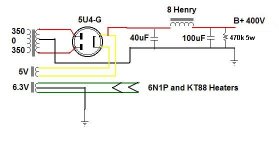
Wiring diagram
OK, here's my wiring diagram for this amp.
I'm a little concerned about the heater wiring.
Can I get a critique from a few people as to the routing? Does it look ok as is, or do some things need to be re-routed?
Thanks in advance.
Glenn
http://webpages.charter.net/porkchop/tube_stuff/KT88_SET_STEREO_WIRING.jpg
Grounding question.
I have a ground point that includes my input jacks and the potentiometers. Then I have a ground point that includes the cathode resistors and bypass caps for all the tubes (2 kt88's and the single 6N1P).
I'm wondering if I should move the cathode resistors and bypass caps for the 6N1P from the ground thats for the KT88's, to the input jacks/pots ground? Does this make any difference?
I'm using a 1/8" aluminum top plate as the chassis, and I have 3 ground points on that chassis (power supply, tube cathode connections, and input grounds).
Maybe I should leave it as is and see how it sounds first?
Any suggestions would be appreciated.
Thanks.
Glenn
I connected the earth ground from my AC cord to the top plate. I kept my other ground points separate and not grounded to the top plate and then connected them all to the single chassis ground using heavy gauge solid copper with a separate run from each ground point. It seemed to work that way with no audible hum from the amps.
Sherman said:I connected the earth ground from my AC cord to the top plate. I kept my other ground points separate and not grounded to the top plate and then connected them all to the single chassis ground using heavy gauge solid copper with a separate run from each ground point. It seemed to work that way with no audible hum from the amps.
Yes, I've seen this done in other amps. A large copper buss wire used for grounding various stages. I myself have never used this method. I've always used localized ground points on the chassis for each section, and have never had a hum problem either.
I guess I'll keep working this way until I first get the amp running, then we'll see how it sounds and go from there.
I appreciate the information though, as I may wind-up using that method if the amp is too noisy.
Thank you.
Glenn
- Status
- This old topic is closed. If you want to reopen this topic, contact a moderator using the "Report Post" button.
- Home
- Amplifiers
- Tubes / Valves
- Stereo build- Mikael Abdellah's KT88 SE amp