ecl86 - quick and dirty
Hi folks..
I bought an old blaupunkt radio. It has all the guts to make a stereo SE ECL86 amp (2x ecl86, opt's and power supply)
The radio still works and sounds descent, but i don't listen to radio and don't need the amp part.
I want to make a gift. So i have these components ready. Now i have to arrange some caps and resistors around them.
Any thoughts how i can squeeze the best out of it in a simple way?
There's a lot of talking about the rh84 amp, but i can't seem to find out what the rh means...
The Stoetkit is a push pull design, which means you would need different output transformers and power transformer (one pair of extra ECL86 tubes), which are quite expensive.
Ik also have a little SE amp with ECL86 which came out of an old record player. I have the schematic published on my webSite.
Low Budget Pat
There are some more schematics on the Internet for a single ended ECL 86. For example:
ECL86 stereo
Note: It's quite fun with such a simple tube to build an amplifier, but you will need higher efficiency loudspeakers. It will only produce about 3 to 4 watts per channel.[/I
Found this one. Forgot to tell you i had that em87 tube in the radio too")
There is an em84 in there too, but my guess is that it's dead.
http://www.loewenkatapult.de/Schema_ecl86.htm
Any thoughts on the quality of the schematic?
My cd player has a capacitor coupled out, my guess is i can ditch the input caps and just take a 100k pot and 1k gridstopper?
I looked at the opt's and they seem to have that extra feedbach winding on them.
I just can't fugure out why it has that cap over the primary of the opt...
Bas
I don't know of the quality of the schematics. As far as technical aspects of electronics, I'm a bit of a nono.
I would like to rebuild/rewire my amplifier and have been looking for an alternative schematic. Have had contact with Marco from Marco's knutselsite. Just send him a mail, he is quite helpfull.
I would like to rebuild/rewire my amplifier and have been looking for an alternative schematic. Have had contact with Marco from Marco's knutselsite. Just send him a mail, he is quite helpfull.
wanted to salvage the tranny's
so i measured them to see the connections..
got some results that seem awkward to me. on the tranny there are a resistor and a capacitor
i made a quick pic of the results. any thoughts? especially the 2.2k measure seems really odd (it had an em87 output indicator! the leads seem to go to that part of the radio)
Attachments
Got reallly lucky yesterday. Went to this computer dump i knew had a box of tubes, so i pulled some out. I saw the posted schematic with a ez80 rectifiction. Saw one in the box, next to an ez 81. Further a box with sylvania ecc83 and an em80.
I'm new to tubes, so the nubers rang some bells, but didn't know exactly what i bougt.
payd 10 euro (seemed fair) for the four. I had to go to the shop in front to pay. There i saw this very cool metal housing. Price: 12 euro! It's about 40x40x15 cm. Indistrial grey flake painting.
Got home, opened the boxes and found out it was a pope ez80, philips ez81, and egro em80 (tuning eye). The ecc 83 turned out to have a pcl805 in it.
didn't know what it was so checked the internet: found this:
pcl85 regulator
How cool is that? Now i have all the components to make a really nice piece of construction! Tube rect, tube regulated ecl86 amp!
Can't wayt to begin!
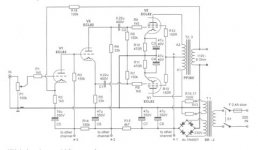
Kolster Philadelphia ECL86 schematic
Hi Beamet.
This old thread smells like the dust of a grandpa's radio rescued from the attic
I am in the same situation: I have an old Kolster Iberica record Player and I want to use the two German made ECL86, and the output iron, to build an amplifier for a friend.
I think will buy a new power transformer, because that one has the 220V straight to the ground
Which schematic did you finally used in your design?
This is the schematic of the Kolster:
An externally hosted image should be here but it was not working when we last tested it.
Last edited:
Found this one. Forgot to tell you i had that em87 tube in the radio too
There is an em84 in there too, but my guess is that it's dead.
ECL86 V2
Any thoughts on the quality of the schematic?
My cd player has a capacitor coupled out, my guess is i can ditch the input caps and just take a 100k pot and 1k gridstopper?
I looked at the opt's and they seem to have that extra feedbach winding on them.
I just can't fugure out why it has that cap over the primary of the opt...
Bas
The first stage of this schematic is horrible and will not work with a CD source. See the 10M resistor? It is "grid bias". You can replace it with normal cathode bias, and make it work.
I've found that there is a 1uF condenser in parallel with the cathode resistor at the input triode that was not shown at the original schematic.
What is your opinion about the following mod? Would it be ok to increase the value of the 10nF coupling capacitor? I will appreciate any other idea:
What is your opinion about the following mod? Would it be ok to increase the value of the 10nF coupling capacitor? I will appreciate any other idea:
An externally hosted image should be here but it was not working when we last tested it.
Last edited:
you guys might be interested in this amplifier writeup on the american version on that tube.
6GW8 El-Cheapo amplifier, "Phoenix"
6GW8 El-Cheapo amplifier, "Phoenix"
Hi folks,
for your own security's sake, please avoid these autoformers in the power supply circuitry! Always use a transformer with separate primary and secondary windings!
Btw, the scarce and expensive ECL86 tube can easily be replaced by its TV receiver counterpart PCL86, if you have a heater supply of about 14 volts handy.
Best regards!
for your own security's sake, please avoid these autoformers in the power supply circuitry! Always use a transformer with separate primary and secondary windings!
Thank You for the important advice!
Yes, I have already dismounted it, and I am not going to play with it until I got a safe transformer.
For pic lovers:
I think that an isolation transformer in front of the existing transformer will be cheaper than finding a replacement transformer. I have not taken measures because I have already dismounted it, but I guess that 50VA will be enough
N-68X Triad Magnetics Power Transformers
An externally hosted image should be here but it was not working when we last tested it.
An externally hosted image should be here but it was not working when we last tested it.
I think that an isolation transformer in front of the existing transformer will be cheaper than finding a replacement transformer. I have not taken measures because I have already dismounted it, but I guess that 50VA will be enough
N-68X Triad Magnetics Power Transformers
- Status
- This old topic is closed. If you want to reopen this topic, contact a moderator using the "Report Post" button.
- Home
- Amplifiers
- Tubes / Valves
- ECL86 - quick and dirty