Ok, a generic question here, as I get deeper into the "paralysis thru analysis” syndrome.
Based on the experience of the group, what are the general sonic differences between a plate loaded SE and a cathode loaded SE ? I’ve only seen a few cathode loaded designs in spite of how good they look on paper. I’ve also read a review by Lynn Olsen (I think) on a cathode loaded SE a while ago, and he seemed to indicate that it kept the SE magic while not having some of there shortcomings.
Anyhoo…I would really be interested in what you guys think.
Casey
It seems they look good on paper until you start designing the driver - which needs to swing the full plate loaded drive plus the plate loaded output voltage... fun, fun, fun
Good point..assuming the driver issues are resolved, is there any "sonic" downside with the "follower" output stage ? There seems to be some potential advantages, on paper anyway.
Thanx PRR..a very good technical discussion.
In that thread you said...
Yeah, long on good impressions and short on hard numbers. He's happy, I'm happy for him. Can I be happy? Hard to know without more info.
...in reference to the Lizzy CF Power Amp. You sort of hit on my dilemma here. The potential seems to be great for a CF power amp, I was hoping to hear from some builders that have done ‘em, and how they defined the sonic “signature”. It “seems” that if you can overcome the difficulties of driving them (no small task) it would be worth the effort.
Casey
valveitude said:Ok, a generic question here, as I get deeper into the "paralysis thru analysis” syndrome.
Based on the experience of the group, what are the general sonic differences between a plate loaded SE and a cathode loaded SE ?
Y'mean with transformer drive so they get the same grid-cathode signal, or anode load vs. cathode *follower*?
In the first case, there is exactly NO difference (note any grid current is kept in the transformer loop and doesn't enter the plate-cathode loop). In the second, you need an absolutely massive voltage drive, preventing it from being used by all but the most absurd designers.
Besides, a cathode follower has such low gain due to local negative feedback. You can apply exactly as much NFB, *or more* if you want, with amplifiers of much smaller signal capacity = lower distortion, with loop NFB. It's not quite the same because you have delay in each stage but a good designer knows how to handle this.
Tim
I don't see a problem with CF amp....
The CF is a current amplifier with close to unity voltage gain...
SO your doing all your voltage gain at the driver stage ...but the CF input grid is not a tough load to drive.... just make sure you get the proper voltage swing....
CHris
The CF is a current amplifier with close to unity voltage gain...
SO your doing all your voltage gain at the driver stage ...but the CF input grid is not a tough load to drive.... just make sure you get the proper voltage swing....
CHris
And the gain of a CF in this application, power tubes having a low mu, is actually substantially lower than 1 for a triode connection. The problem being, your drive requirements increase by it's reciprocal - which means tensof volts for every .1 off of the theoretical gain of 1. You could, however, use a pentode strapped as a CF, that would indeed bring you very close to 1, at the expense of a bootstrapped or independent screen supply.
> gain of a CF..., power tubes having a low mu, is actually substantially lower than 1 for a triode connection.
You can't derive gain from Mu alone (unless you make some assumption about Rl/Rp.
You can derive it from Rp/Mu, but that's the same thing as 1/Gm. So Gm is the simplest way to look at it.
For a given size cathode and grid precision, Mu and Rp vary all over, in the same direction, but Gm does not vary much.
So for a given load impedance, gain is a function of Gm which is a function of tube general size/class, but for "reasonable" tubes it will not vary much.
Also most of the promised benefits of CF operation go-away very quickly as gain goes down (as load becomes not-large compared to 1/Gm).
It can be convenient to define Rk as 1/Gm.
> use a pentode strapped as a CF, that would indeed bring you very close to 1
Pentode strapped as triode is just a triode. Possibly a better triode, because the main thrust of power-tube work was with pentodes; possibly not so good because a pentode can give low drop with medium G1-G2 Mu and a triode must have low Mu for low drop.
Pentode strapped as pentode does not work a lot better, Gm is actually lower, and driving the G2 to track the cathode can be VERY hard work.
> make sure you get the proper voltage swing....
In practice this problem is MUCH larger than it should be.
Take a triode CF with 300V plate supply. Best power is around Rl=2*Rp. Cathode swing will be about 200V peak. THD at large power will be around 5% divided by the feedback factor. Gain will be about Rl/(Rk+Rl). This will come out about 0.9 for many cases. Distortion of the CF alone is about 5%*0.1= 0.5%, nice. But grid swing will be about 1.1*200Vpk or 220V peak. A resistance-coupled voltage amp sees a light load looking into the CF, but still will make up to 5% THD when swinging peak voltages of 20% of the supply voltage. Or: the supply voltage should be 5 times the peak signal voltage for 5% THD.
So given 220V peak to the CF grid, we want 5*220V= 1,100V driver supply! We get ~0.5% THD in the CF, but ~5% THD in the driver. The "sonic signature" will depend very-much on the driver. We have just shifted our troubles from the output stage to the driver.
> You can apply exactly as much NFB, *or more* if you want, with amplifiers of much smaller signal capacity = lower distortion, with loop NFB.
That's the way I see it. The CF configuration only works for ~100% NFB, and for power stages forces an earlier stage to ABSURD signal levels. With plate-loading, you can choose 50%, 100%, 200% NFB, and the driver does not work significantly harder than the no-feedback amplifier.
I really appreciate all the feedback …I hope I can encourage some more.
Basically from what I understand from what I’ve read here and from the links provided in this thread , cathode loading in of itself is good, the requirements to drive the follower not so much. The sonic signature of the whole is, more or less, the sonic signature of the diver circuit.
If this is correct, I think a cathode loaded amp is just what I need for a rather unique application, a ribbon design I have been working on. I discussed the basic design and the amp I want to build for them, and had my thinking changed in these threads…
http://www.diyaudio.com/forums/showthread.php?s=&threadid=60561
http://www.diyaudio.com/forums/showthread.php?s=&threadid=60854
I want to build a dual (side by side) .75”x 36” ribbon with a projected efficiency of 103~106dB. By going with dual ribbons I double the radiation area, extending the bottom end, but I also narrow the dispersion at the top end because the effective width is from outside edge to outside edge. I could be too clever by half, but I think I solved the problem. By shunting one of the ribbons with a suitable capacitor, I have a one component crossover. In order to get away with that, I need an amp with a low output impedance. But I want a SE tube amp..normally not workable, but I think this circuit is the answer…
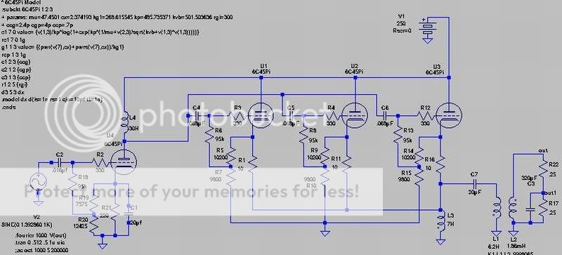
The value of the cap shunting one of the .25 ohm resistors (ribbon) on the load is a 320uF cap. This starts bypassing the ribbon and lowering the load at 2khz. Simulating this circuit shows the amp is ruler flat to 10khz and down ~.4dB at 20khz (the cathode resistors are causing the dip). Not only can it handle my funky load it also has MUCH lower distortion.
This is the distortion log of the anode loaded amp described in the first thread I linked at 4 watts @ 1khz…
…and this is the amp shown here pushing just under 4.8 watts ( same voltage, lower load do to cap)…
Basically it’s a Brian Clark inspired voltage amp driving a follower. Because the “spud” has a much easier load, its distortion is much lower.
Unless I hear a compelling reason why I shouldn’t build it, I will start sourcing parts and winding iron.
Casey
Basically from what I understand from what I’ve read here and from the links provided in this thread , cathode loading in of itself is good, the requirements to drive the follower not so much. The sonic signature of the whole is, more or less, the sonic signature of the diver circuit.
If this is correct, I think a cathode loaded amp is just what I need for a rather unique application, a ribbon design I have been working on. I discussed the basic design and the amp I want to build for them, and had my thinking changed in these threads…
http://www.diyaudio.com/forums/showthread.php?s=&threadid=60561
http://www.diyaudio.com/forums/showthread.php?s=&threadid=60854
I want to build a dual (side by side) .75”x 36” ribbon with a projected efficiency of 103~106dB. By going with dual ribbons I double the radiation area, extending the bottom end, but I also narrow the dispersion at the top end because the effective width is from outside edge to outside edge. I could be too clever by half, but I think I solved the problem. By shunting one of the ribbons with a suitable capacitor, I have a one component crossover. In order to get away with that, I need an amp with a low output impedance. But I want a SE tube amp..normally not workable, but I think this circuit is the answer…
The value of the cap shunting one of the .25 ohm resistors (ribbon) on the load is a 320uF cap. This starts bypassing the ribbon and lowering the load at 2khz. Simulating this circuit shows the amp is ruler flat to 10khz and down ~.4dB at 20khz (the cathode resistors are causing the dip). Not only can it handle my funky load it also has MUCH lower distortion.
This is the distortion log of the anode loaded amp described in the first thread I linked at 4 watts @ 1khz…
An externally hosted image should be here but it was not working when we last tested it.
…and this is the amp shown here pushing just under 4.8 watts ( same voltage, lower load do to cap)…
An externally hosted image should be here but it was not working when we last tested it.
Basically it’s a Brian Clark inspired voltage amp driving a follower. Because the “spud” has a much easier load, its distortion is much lower.
Unless I hear a compelling reason why I shouldn’t build it, I will start sourcing parts and winding iron.
Casey
> By shunting one of the ribbons with a suitable capacitor, I have a one component crossover.
Or drive parallel, series one strand with a choke. The plate-loaded amp you propose will rise in gain as the impedance rises.
I also have real doubts this ribbon is, or can be, "flat". The way I suss it out, the power response falls 3dB/oct, the on-axis response is near-flat because of rising directivity. Which does the ear hear? It depends. Mostly both, which is why the mainstream of hi-fi has aimed for (not always hit) near-omni (or hemi) response over most of the audio band, with stuff like 1" round tweeters.
I could see you needing a "slope" control to skew the response.
I can imagine piercing highs if you sit within 3 heights (within 10 feet from a 3-foot tall source).
The wise path would be to build the speaker, drive it with any handy amp (if it is as sensitive as you hope, you could use resistors to match the ~0.5 ohms to typical amp outputs), and see what you hear, then design the complementary amplifier. You may find that 4 watts is not enough. Or way too much. You may find it likes current drive rather than voltage drive.
I would also suggest a 0.75"x72" array as less bipolar and possibly a better fit to an 8-foot listening room. Now the room acts as a 2-D bucket, the inverse-square law is repealed over the whole audio range, not just above ~300Hz and less than 10 feet away.
> Unless I hear a compelling reason why I shouldn’t build it, I will start sourcing parts and winding iron.
Compel you? Never. However, wind the 50H choke first, see what the impedance really is. SPICE does not know that real chokes have capacitances and internal resonances. Your driver impedance may be low enough to swamp these out, but the choke parasitics are the hidden pitfall of choke-loaded voltage amps.
Or drive parallel, series one strand with a choke. The plate-loaded amp you propose will rise in gain as the impedance rises.
I considered that, but decided that dealing with a .5 ohm load was going to be difficult enough, a .125 ohm load would be more so.
I also have real doubts this ribbon is, or can be, "flat". The way I suss it out, the power response falls 3dB/oct, the on-axis response is near-flat because of rising directivity.
Well, the “flat” I was referring to was the amp, not the ribbon. I know of no driver that has a flat “in room” response without eq.
I can imagine piercing highs if you sit within 3 heights (within 10 feet from a 3-foot tall source).
My experience with ribbons doesn’t predict this. I had a lot of experience with the Apogee Caliper (entry level speaker with a 36” ribbon/ 6” mid-bass) and I never had anything remotely “piercing” emanate from them. “Smooth” “lush” “liquid” are terms that come to mind describing anything from 500hz up (the bottom octaves sucked in comparison), regardless of listening distance. My boss even had me set them up in a 8’x8’ room (no kidding) and even sitting on top of them the upper registers were magic.
The wise path would be to build the speaker, drive it with any handy amp (if it is as sensitive as you hope, you could use resistors to match the ~0.5 ohms to typical amp outputs), and see what you hear, then design the complementary amplifier. You may find that 4 watts is not enough. Or way too much. You may find it likes current drive rather than voltage drive.
At what point have I said anything that would indicate I would take a “wise” path
")
I would also suggest a 0.75"x72" array as less bipolar and possibly a better fit to an 8-foot listening room.
Re-reading my earlier description(s) of the proposed ribbon, I see I left out a key point. I intend to back load the ribbon into a transmission line. Not so much to extend the bottom end (it will a little), but to “gently” absorb the backwave. There is no question in my mind that the ultimate ribbon set up is a dipole in a big room 6’ or so from the wall, not having the big room I need to go monopole.
Casey
So let's see, you just have a whopping low impedance to drive? Is that what this is about? Nothing weird about that, everything else is exactly the same as a normal amplifier, you just need a transformer wound about 50 times lower impedance with wire that much heavier. You'll want the OPT right at the ribbon since miliohms are your enemy; soldered or securely crimped connections only. Fortunately the high external voltage makes for easy distribution, if not dangerous if something starts chewing on the wires!
Tim
Tim
So let's see, you just have a whopping low impedance to drive? Is that what this is about?
Actually it's more of an issue of a tube amp that has suffeciently low output impedance that it can handle a 2:1 load difference without a change in output voltage. The cap shunting one of the ribbons @ 2khz swings the load from .5 ohms down to .25 ohms. The simulations I ran have shown a significant drop of output voltage with anode loaded circuits.
> dealing with a .5 ohm load was going to be difficult enough, a .125 ohm load would be more so
A Weller soldering gun is "wound" (half-turn) for a 0.000,1 ohm secondary resistance. It isn't hi-fi (pure heat) but many transformer problems diminish with impedance, as long as you do your homework (Weller uses a 3/8" copper tube for the "winding").
As Tim says, speaker cables are problematic. Welding cables may be a start, though you better estimate the inductance. Or distribute the hi-Z side: with your cap-coupled CF at least the DC voltage is small. I guess I expect you will put an amp ON the speaker, and do distribution at line-level (arg! added capacitance!).
I guess I expect you will put an amp ON the speaker, and do distribution at line-level (arg! added capacitance!)
I'm thinking along the lines of locating the follower section at the speaker, and the voltage amp near the source(s).
I'm thinking along the lines of locating the follower section at the speaker, and the voltage amp near the source(s).
Oopsie.. I meant to say I plan to put the followers output transformer at the ribbon, not the follower (note to self...use the preview function)
valveitude said:
Actually it's more of an issue of a tube amp that has suffeciently low output impedance that it can handle a 2:1 load difference without a change in output voltage.
Pffbt, happens all the time with speakers. Heck, 2:1 is better than most, IIRC!
If you get Zo down to say 12-50mohms, that'll be just fine. Pentode with 20-30dB NFB will do well. Like I said, you'd better use heavy, well bonded wire or buss between the OPT and ribbon.
Given the high frequency range and heavy wire required, you'll probably want either flat wire (strip) for the secondary, or perhaps doing away with a conventional EI iron core altogther. Mind the lower inductance if you do; here a CF may be useful, if not in essence using a 250 ton dump truck to plow a flower garden.
You could also use a transformer at the ribbon to reduce 8 or 16 ohms to the required impedance and power it with a conventional amplifier.
Tim
An old idea that keeps popping up in my head:
PL504 triode CF at Ua= 150V and Ia 110mA loaded with and 11:1 (or so) airgapped autoformer.
Driver stage could be a PC86/IRF820 hybrid µ-follower, should be capable of at least +-100V peak swing if fed with 300V B+.
Someday when my significant other is at work and the cat is asleep I´ll sit down and wind those autoformers...
Or, we could feed the whole thing from 300V and put some kind of meaty CCS between the PL504 cathode and ground, then use mains toroid transformers as parafeed OPT´s.
That would allow direct coupling between the input and output stages.
Nah, I think I would prefer those atoformers. More OTL-like in some way...
Quick, cheap and dirty just as yours truly
/Daniel
- Status
- This old topic is closed. If you want to reopen this topic, contact a moderator using the "Report Post" button.
- Home
- Amplifiers
- Tubes / Valves
- Anode Loading Vs. Cathode Loading ?