I hope I am not starting a religious war by asking such a question, but are there good reasons to use tube rectification vs. solid state? (apart from subjective preferences)
The circuit to be powered is a mix of solid state and tubes. CCS's etc are solid state, I have chosen gas discharge stabilizers over zeners for noise performance (1/F noise, critical as this is a high-mu app), and also tubed mu-stage (as I feel good triode always better an op-amp), but I don't know about the right reasons for chosing the right rectumfrying in the PSU. Thing is I'll favor SS over tubes if performance is equal... it'll save me at least one toroid... Won't look as nice, sure, but I'm trying to make music on a budget here.. not art..
The circuit to be powered is a mix of solid state and tubes. CCS's etc are solid state, I have chosen gas discharge stabilizers over zeners for noise performance (1/F noise, critical as this is a high-mu app), and also tubed mu-stage (as I feel good triode always better an op-amp), but I don't know about the right reasons for chosing the right rectumfrying in the PSU. Thing is I'll favor SS over tubes if performance is equal... it'll save me at least one toroid... Won't look as nice, sure, but I'm trying to make music on a budget here.. not art..
The main advantage to a tube rectifier is slow warmup. Balanced against this are high DC drop, lower reliability, higher heat, lower efficiency, and poor regulation.
For all the theoretical noise benefits, in a series of measurements I've been doing on DC output rails (as opposed to measurements within the rectifier block), I haven't seen any advantage to tubes.
For all the theoretical noise benefits, in a series of measurements I've been doing on DC output rails (as opposed to measurements within the rectifier block), I haven't seen any advantage to tubes.
cathode_leak said:I hope I am not starting a religious war by asking such a question, but are there good reasons to use tube rectification vs. solid state? (apart from subjective preferences)
Nope. None at all. Hence why it starts wars of religious intensity.

About the only reason anyone uses a tube diode is nostalgic... and the oft-repeated claim that soft start has some advantage somehow.
The circuit to be powered is a mix of solid state and tubes. CCS's etc are solid state, I have chosen gas discharge stabilizers over zeners
Za??! Gas tubes are wayy worse, for the express reason that you CANNOT connect a large capacitor across one. I dare you to try it!
Tim
Recently I tried out gas regulators to supply the driver stage in one of my amplifiers. Although I couldn't hear any hiss or noise, the sound seemed harder and tiring to listen to over long periods. Some fine detail in the music was missing. Reverting to the old (unregulated) power supply circuit brought the music back to life.
I have also tried mercury and silicon rectifiers with varying degrees of the same effect. To my ears, tube rectifiers sound significantly nicer than the alternatives.
A bit dissapointing really as I liked all the pretty colours...
I have also tried mercury and silicon rectifiers with varying degrees of the same effect. To my ears, tube rectifiers sound significantly nicer than the alternatives.
A bit dissapointing really as I liked all the pretty colours...
Re: Re: Rectifiers: Tube vs Solid state..
Thanks for the replies. Seems like i'll have solid state rect. then.
Regarding zeners vs VRs I remember reading somewhere (on this forum.. couldn't find it now) that Zeners have a somewhat white noise but with increasing 1/F noise, wich can and will be a problem in high-mu apps such as phonostages, dac O/P, etc.. And thus zeners are better suited for amps and such, while VRs are the better choice for mu-stages. This is wrong, eh?
Relaxation oscillator? nop. I need it for regulating
Thanks for the replies. Seems like i'll have solid state rect. then.
Regarding zeners vs VRs I remember reading somewhere (on this forum.. couldn't find it now) that Zeners have a somewhat white noise but with increasing 1/F noise, wich can and will be a problem in high-mu apps such as phonostages, dac O/P, etc.. And thus zeners are better suited for amps and such, while VRs are the better choice for mu-stages. This is wrong, eh?
Sch3mat1c said:Za??! Gas tubes are wayy worse, for the express reason that you CANNOT connect a large capacitor across one. I dare you to try it!
Tim
Relaxation oscillator? nop. I need it for regulating
SY said:Well, mainly, take advantage of the fact that zeners (and other good references) can be bypassed.
i wonder what would such an "other good reference" be..?
Edit: I found the forum text i was referring to in the last post:
tubetvr said:
....snip...
VR tubes have much lower dynamic resistance than high voltage Zeners and therefore make better regulators stand alone than Zeners. In noise sensitive applications it should not be forgotten that Zeners give an almost white noise but with increasing 1/F noise below a few 100Hz, therefore it is not that easy to make them quiet in applications where this 1/F noise can be a problem for instance in RIAA stages, VR tubes dont have this 1/F noise problem, (1/F noise in Zener based regulators was a big issue when I was designing low phase noise oscillators for microwave)
...snip...
Regards Hans
cathode_leak said:
i wonder what would such an "other good reference" be..?
Bandgaps, avalanches, LEDs, even current sources stacked on a resistor.
Again, the device itself is not as important as the resulting noise from the implementation of the device!
One thing SY has pointed out is that a zener can have a cap hung across it. Basically, if you can make the circuit quiet you are good to go. It's easier when you can silence the noise at the source.
Note: When you install a capacitor across a zener, you have just reduced the AC impedance to a much lower value. So much for the noise. The rest of the regulator circuit can reduce this further. Add output filtering to complete a rather good voltage source (within the current limits).
-Chris
Note: When you install a capacitor across a zener, you have just reduced the AC impedance to a much lower value. So much for the noise. The rest of the regulator circuit can reduce this further. Add output filtering to complete a rather good voltage source (within the current limits).
-Chris
anatech said:One thing SY has pointed out is that a zener can have a cap hung across it. Basically, if you can make the circuit quiet you are good to go. It's easier when you can silence the noise at the source.
Note: When you install a capacitor across a zener, you have just reduced the AC impedance to a much lower value. So much for the noise. The rest of the regulator circuit can reduce this further. Add output filtering to complete a rather good voltage source (within the current limits).
-Chris
Let me see if I got this right.. The attached drawing is only conceptual, no numbers here; drawing 1 shows a diode bridge with a cap hung across. In drawing 2, i add a very basic cascaded depletion mode CCS, drawing 3 attaches a zener after the CCS, forming a shunt regulator, bypassed by a cap.. in drawing 4 I added a RC filter at the output.. Does it look "OK" for a solid state PSU powering tubes? Should I maybe use separate RC filters for each channel?
Attachments
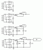
cathode_leak said:Let me see if I got this right.. The attached drawing is only conceptual, no numbers here; drawing 1 shows a diode bridge with a cap hung across. In drawing 2, i add a very basic cascaded depletion mode CCS, drawing 3 attaches a zener after the CCS, forming a shunt regulator, bypassed by a cap.. in drawing 4 I added a RC filter at the output.. Does it look "OK" for a solid state PSU powering tubes? Should I maybe use separate RC filters for each channel?
Uh, if you want to defeat the purpose of regulating in the first place, uh, I guess so.
Also begs the question of dragging out SS with great dynamic range, only to use it to waste all the power supplied?
I hate shunt regs...If you rearrange #3 to a pass regulator, it'll work wonderfully.
Tim
I used silicon rectifiers in my PP 807 amp. I had to install a B+ switch, due to the voltage rising to over 600V with tubes cold (normally 500V with load). Now when I turn the B+ on, there is a momentary surge of about 150mA per tube for a couple of seconds. It makes me cringe to see the current meter slam into the end of the scale...
So my vote is for SS diodes, with a TV damper diode for slow warm up. If I had any room on the chassis this is what I would do...
Apart from that, I like to use tube rects just because they look cool!
So my vote is for SS diodes, with a TV damper diode for slow warm up. If I had any room on the chassis this is what I would do...
Apart from that, I like to use tube rects just because they look cool!
Apart from that, I like to use tube rects just because they look cool!
I must be the uncoolest person in this thread. If SS could do the job of rectifying halfway decent i'd never dream of using tubes. Much less Mercury. But then, uncool or not, i tend to follow my ears. And not to ask others about what sounds good.
Hi analog_sa,
Whatever you use to rectify loses it's "sound" after any half decent regulator stage. That is unless the rectifier type causes the regulator to "drop out" at some point. Then you are talking poor design, another issue all over.
I think we are talking of bypass caps here?
-Chris
Whatever you use to rectify loses it's "sound" after any half decent regulator stage. That is unless the rectifier type causes the regulator to "drop out" at some point. Then you are talking poor design, another issue all over.
I think we are talking of bypass caps here?
-Chris
Whatever you use to rectify loses it's "sound" after any half decent regulator stage
I have heard this claim many times, both related to SS and tube circuits, but have failed to find it true in practice.
IME rectifier (or even PC) sound passes well through regulators. And why shouldn't it? At those frequencies regulators are generally incapable to regulate much and parasitic capacitances become open gates for noise.
Konnichiwa,
Are you actually talking about an assumption based on so-called "common sense" (that dreary bog of sullen prejudice and inertia) or are you refering to facts?
Let make a few thoughts here.
The current waveform in the transformer will differ (quite radically actually) between a valve rectifier which has issues of current saturation and high internal impedance and a solid state rectifier.
Could that lead to differences in radiated magnetic field and the spectrum of noice leaked into the circuit [ground] (other than that through the +B line)?
Further, the switching behaviour between the diodes differs drastically. Could that lead to differenced in radiated noise and noise leaked into the circuit [ground]?
(the answer btw is a resounding yes)
If so, can you garantee that with "non-poor designs" this does not happen?
Note, that the regulator is not even in the picture, it's presence or absence if no consequence in our scenario.
Sayonara
anatech said:Whatever you use to rectify loses it's "sound" after any half decent regulator stage. That is unless the rectifier type causes the regulator to "drop out" at some point. Then you are talking poor design, another issue all over.
Are you actually talking about an assumption based on so-called "common sense" (that dreary bog of sullen prejudice and inertia) or are you refering to facts?
Let make a few thoughts here.
The current waveform in the transformer will differ (quite radically actually) between a valve rectifier which has issues of current saturation and high internal impedance and a solid state rectifier.
Could that lead to differences in radiated magnetic field and the spectrum of noice leaked into the circuit [ground] (other than that through the +B line)?
Further, the switching behaviour between the diodes differs drastically. Could that lead to differenced in radiated noise and noise leaked into the circuit [ground]?
(the answer btw is a resounding yes)
If so, can you garantee that with "non-poor designs" this does not happen?
Note, that the regulator is not even in the picture, it's presence or absence if no consequence in our scenario.
Sayonara
I am fully aware of this. I have proved this to myself empirically, in practice on both tube and solid state gear. When designing a power supply for low current stages, add a resistance in series between the rectifiers and input cap. This takes the "edge" off the waveform (in the xformer too). Now your waveform looks more tube - like. This is due to the internal resistance that is natural in a tube. Gee, the transformer current waveform is now the same as well. Imagine that!
If your regulator is passing audio and HF signals, it is defective . Don't talk to me until you fix it. My comments relate to properly designed supplies. I have fed a good regulator both smoothed and straight filtered from silicon diode sources. A good regultator does a fine job of giving you clean DC, better with smoothed (talking uV here now).
Is it possible the sound difference is due to the different cap value on the output of a regulator that people tend to use? There are still many variables here without throwing poorly design regultors into the mix.
-Chris
Konnichiwa,
My comments where with complete disregard to filtering/regulation etc. The +B itself does not come into play with the issues I raised, so the regulator does not come into play, whatever it passes or not.
I am strictly refering to "ground" contamination.
Sayonara
anatech said:If your regulator is passing audio and HF signals, it is defective . Don't talk to me until you fix it.
My comments where with complete disregard to filtering/regulation etc. The +B itself does not come into play with the issues I raised, so the regulator does not come into play, whatever it passes or not.
I am strictly refering to "ground" contamination.
Sayonara
- Status
- This old topic is closed. If you want to reopen this topic, contact a moderator using the "Report Post" button.
- Home
- Amplifiers
- Tubes / Valves
- Rectifiers: Tube vs Solid state..