hi all
I recently read US patent 2895019 by M.Farber
about compensating opt SE trafos to cancel the constant
flux as in PP transformer.
This is achieved by the use of a choke or
a capacitor and, if true it is a great advance in
SE tube amp design.
I carefully read the patent but I am still very doubtful.
opinions?
thanks
bye
Federico Scarpa
Konnichiwa,
Especially figure 3 (see attached) seesm very workable.
I have recently started working on "electronic chokes", that is mosfet (or BJT) structures that behave like chokes on top of being ripple killers like classic gyrators.
If you take a traditional PP Output Transformer and feed one from a traditional gyrator and the other from a bootstrapped gyrator (electronic choke) and hang your SE valve of the original centertap you have an SE Output at 1/4 of the primary impedance of the original transformer.
Pretty neat way to build cheap SE Amp's with 6AS7 or 2A3 and the like. You could probably get away using certain mains torriods even.... The "PhrugalPhiles" SE Valve Amp in essence.
I like it.
Sayonara
fscarpa58 said:I carefully read the patent but I am still very doubtful.
Especially figure 3 (see attached) seesm very workable.
An externally hosted image should be here but it was not working when we last tested it.
I have recently started working on "electronic chokes", that is mosfet (or BJT) structures that behave like chokes on top of being ripple killers like classic gyrators.
If you take a traditional PP Output Transformer and feed one from a traditional gyrator and the other from a bootstrapped gyrator (electronic choke) and hang your SE valve of the original centertap you have an SE Output at 1/4 of the primary impedance of the original transformer.
Pretty neat way to build cheap SE Amp's with 6AS7 or 2A3 and the like. You could probably get away using certain mains torriods even.... The "PhrugalPhiles" SE Valve Amp in essence.
I like it.
Sayonara
Konnichiwa,
One of my tricks to make my Push-Pull amplifiers sound a lot more "SE" is to allow or rather to deliberatly introduce a modest degree of DC imbalance, enough to shift us a bit up the BH curve and to move the problem region from "minimal signal" levels into the 0.1W++ region. The same can be done for the compensated SE.... ;-)
Sayonara
Yvesm said:You loose that kind of "magnetic bias" from DC current in the tranny that help to stay in the flatter portion of the iron Mu curves

Nothing for nothing, this could produce a SE amp sounding like a PP one
One of my tricks to make my Push-Pull amplifiers sound a lot more "SE" is to allow or rather to deliberatly introduce a modest degree of DC imbalance, enough to shift us a bit up the BH curve and to move the problem region from "minimal signal" levels into the 0.1W++ region. The same can be done for the compensated SE.... ;-)
Sayonara
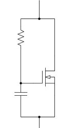
An FET gyrator
I have used this very simple circuit several times. It works amazingly well considering its simplicity (depends mostly on the choice of FET).
DC Voltage drop is more or less equal to Gate Threshold (typically 5-10VDC) think of an L in series with a zener.
I have not developed an equation for the equivalent value of L, it is dependent on transconductance and operating point. Start with a R of 50K or so and a C of 10uF this will get you low in the audio band.
Power switching FETs are a poor choice, too high a gate charge. Higher transconductance is better of course.
Attachments
Kuei Yang Wang said:Konnichiwa,
One of my tricks to make my Push-Pull amplifiers sound a lot more "SE" is to allow or rather to deliberatly introduce a modest degree of DC imbalance, enough to shift us a bit up the BH curve and to move the problem region from "minimal signal" levels into the 0.1W++ region. The same can be done for the compensated SE.... ;-)
Sayonara
Agreed for unbalance deliberatly introduced in a "compensated" SE or even in a PP, however I don't know how the iron will react when passing by zero "bias" at some points in the cycle
In a "classic" SE design, the OPT may be estabished so that DC induction is higher than peak AC in order it never reach zero.
Did you experienced that ? Do you use a (small) gap in this situation ?
I bet "Konnishiwa" is something like "Hi there", isn't it ?
Yves.
hi,
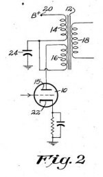
I agree that circuit of fig.3 works.
but I feel cir of fig.2 will never work.
bye
Federico
Especially figure 3 (see attached) seesm very workable.
I agree that circuit of fig.3 works.
but I feel cir of fig.2 will never work.
bye
Federico
Attachments
fscarpa58 said:but I feel cir of fig.2 will never work.
The amp-turns cancel, and the cap prevents voltage appearing on the top winding; unforunately, it also prevents volts from appearing on the bottom winding, through transformer action.
Tim
Figure 2 merely places an LC filter on the core of the OPT. I don't see why this would not work?
As regards the lower part of the BH curve being less linear, I'm not sure what real practical difference BH linearity makes as line level transformers, including TVCs, sound good to my ears. Perhaps these latter would sound better with an air gap and a bit of DC through them? Mind you, remanence ensures that the linearity of the most linear region of the BH curve is not so linear.
As regards the lower part of the BH curve being less linear, I'm not sure what real practical difference BH linearity makes as line level transformers, including TVCs, sound good to my ears. Perhaps these latter would sound better with an air gap and a bit of DC through them? Mind you, remanence ensures that the linearity of the most linear region of the BH curve is not so linear.
hi all
concatenation.
will see zero ohm. so, no signal.
Exactly, Sch3mat1c
I simulated fig.2 configuration and it does not work.
bye Federico
things appear more complicate due to the presence of coreI don't see why this would not work?
concatenation.
in fact, Silurato, a zero Ohm load regard AC, and the output tubeThis is my doubt for fig.2: doesn't the "bypassed" half of the primary appears like a "parasitic load"?
will see zero ohm. so, no signal.
unforunately, it also prevents volts from appearing on the bottom winding, through transformer action.
Exactly, Sch3mat1c
I simulated fig.2 configuration and it does not work.
bye Federico
in fact, Silurato, a zero Ohm load regard AC, and the output tube
will see zero ohm. so, no signal.
Dont'forget the secondary winding. The reflected impedance is the sum of RL (n1/2)squared and Rcap (n2/3) squared. This is because the conservation of energy law V1*I1=V2*I2+V3*I3
Exactly, Sch3mat1c
I simulated fig.2 configuration and it does not work.
Why trust spice more than simple maths? To dissipated any doubt I run a simulation and in a short time I'll post some results pictures at this address:
http://213.156.45.208/primo
just below the Farber patents.
Funky, mad, computer era. PC is more reputed than math. and phys.
Do You really trust more Bill Gates than Euler or Einstein?
Piergiorgio
Farber circuit Spice simulation
Here below the screenshots of the simulation performed on a typical SE application:
http://213.156.45.208/primo/SimulazioniFarber.asp
Here below the screenshots of the simulation performed on a typical SE application:
http://213.156.45.208/primo/SimulazioniFarber.asp
Re: Farber circuit Spice simulation
Konnichiwa,
Please repeat the simulation using a series resistance between generator and transformer which approximates the anode impedance of a normal triode (say 1K).
Sayonara
Konnichiwa,
plovati said:Here below the screenshots of the simulation performed on a typical SE application:
Please repeat the simulation using a series resistance between generator and transformer which approximates the anode impedance of a normal triode (say 1K).
Sayonara
here:
same conditions, 1K tube resistance, not so different.
Stop simulation, turn on the solder iron.
Piergiorgio
An externally hosted image should be here but it was not working when we last tested it.
same conditions, 1K tube resistance, not so different.
Stop simulation, turn on the solder iron.
Piergiorgio
Konnichiwa,
Might do that. I have a pair of PP Outputs I can seperate the centertap....
Sayonara
plovati said:here:
An externally hosted image should be here but it was not working when we last tested it.
same conditions, 1K tube resistance, not so different.
Stop simulation, turn on the solder iron.
Might do that. I have a pair of PP Outputs I can seperate the centertap....
Sayonara
try also this:
http://www.audiocostruzioni.com/forum/topic.asp?TOPIC_ID=1159
permanent magnet instead of addictional winding. It is an original (to my better knowledge) idea and should works.
Yes is in Italian, but with a little effort (and translator SW) You can understand it. The only important thinks is the drawing, from it You can catch the whole idea.
On the other hands, this site in in English, and we italians experiment every days this handicap, so now yours turn.
Piergiorgio
http://www.audiocostruzioni.com/forum/topic.asp?TOPIC_ID=1159
permanent magnet instead of addictional winding. It is an original (to my better knowledge) idea and should works.
Yes is in Italian, but with a little effort (and translator SW) You can understand it. The only important thinks is the drawing, from it You can catch the whole idea.
On the other hands, this site in in English, and we italians experiment every days this handicap, so now yours turn
.Piergiorgio
Permanent magnet
Sorry, like the compensating current winding the peramnent magnet is quite an old idea. It is used extensively in commercial low voltage relays and has long been available in some brands of DC chokes.
True that I've never seen a commercial output transformer using a permanent magnet but a DC current winding is much more flexible.
There was a time in the first half of the 20th century when magnetic amplifiers were the vogue, these used a controlled saturation transformer leg with a variable DC winding to control the gain between two or more AC windings. Not really fast enough for audio amplifiers but very powerful power supplies and motor drives were built this way.
The constant voltage transformer like those made by Sola still use this basic concept.
Very few really new ideas under the sun. But maybe by using high current transistors to control a current winding you might make a magnetic amplifier that surpasses the wildest dreams of what could be done 50 years ago.
Of course two windings with opposing DC and summing AC will cancel core DC nicely - oops, I think this is called a push-pull amplifier.
- Status
- This old topic is closed. If you want to reopen this topic, contact a moderator using the "Report Post" button.
- Home
- Amplifiers
- Tubes / Valves
- DC compensated SE output transformer