This is only ad idea. Why don't we start to analyze the different building techniques? On line there are several articles regarding tubes and audio theory but only a few regarding the "physical techniques" to build and to wire an amplifier.
I'll like to investigate, with the helps of gurus, in differences between point to point VS pcb VS hibrid technique and will come to some reference techniques ( for PTP and PCB too).
If this 3D will be a permanent one we'll have, in my opinion, two great advantages:
1) a guide for newbies and a "manual" with tips&tricks for layout problems/questions
2)a reference building guide. This , in my opinion, will be a very interesting thing. After that we'll have chosen the best way to wire (point to point and pcb) tubes electronics , if someone will post a new projects or an experiment (making clear which technique he chose) everyone could reproduce it without surprises
I think, anyhow, that hibrid wiring ( grd plane/s+solid wire) can be a good solution. Maybe it doesn't for power stage... I've never try something like this, it's just a thought
Now, what do you think about this idea?
If there is some 3d open about this I apologise...
I found nothing with search
Mark
P2P, anything else is blasphemy! 
I'm too lazy to even want to look at let alone go out and buy, etch and use a PCB. Plus my design sometimes changes a bit.
Heck, I'd use P2P on SS circuits too - it's just that the parts are designed with PCBs in mind, so that's really the only effective way to make use of them. So I do the next best thing and use perfboard.
Tim
For line stages and phono stage I like the idea to have tubes closed in a box. I listened many guys complaining about tubes because they are microphonic. Well, tubes are microphonic! So I don't want that my line stage tubes can be knocked down by sound waves.
Even if I have to build point to point I like the idea to use a mechanical support. In the three pre I've built till now, I used copper-clad boards after removing copper plane. I've connect this board to the chassie using screws but with the sagacity to use rubber fairlead between the board and the chassie. Vibrations in this way are under control. I've discovered in a second moment that this is not an original idea...the only important thing is that it works well
I try also pcb with different results...but I'm sure that this was my fault. I think that there is no reason why a good pcb sound worse than ptp. So how design a very good pcb for audio circuit?
In the first post, I said that I like to try an hybrid technique. I think I'll try to use a copper-clad boards and keep its copper plane using it as a grn plane. I'll do all other connections ptp. Using a double copper-clad board and cutting the two copper planes I'll have 4 copper planes. I'm thinking to separate signal gnd and power gnd...and right from left channel too.
So four gnd plane for the circuit board taht I'll connect to the ground plane of the pover board. How does it look?
@ pedroskova: noise is surely caused by a gnd loop...I'll rebuild the circuit next week ;-)
.Anyhow, shielding the input signal cable, the noise is gone down a lot.
mark_titano said:
In the first post, I said that I like to try an hybrid technique. I think I'll try to use a copper-clad boards and keep its copper plane using it as a grn plane. I'll do all other connections ptp. Using a double copper-clad board and cutting the two copper planes I'll have 4 copper planes. I'm thinking to separate signal gnd and power gnd...and right from left channel too.
So four gnd plane for the circuit board taht I'll connect to the ground plane of the pover board. How does it look?
For my phono stage, I took a single clad board and separated it into two channels by making a grove down the middle with a table saw. From there, all I had to do was drill four holes for the tubes and wire the circuit ptp, dropping leads to ground wherever they fell. Dead quiet.

pedroskova said:
For my phono stage, I took a single clad board and separated it into two channels by making a grove down the middle with a table saw. From there, all I had to do was drill four holes for the tubes and wire the circuit ptp, dropping leads to ground wherever they fell. Dead quiet.
So it doesn't look a bad idea heheheh
OT: for the amministrator... does exist a time limit to edit posts?
Mark
I like the idea to have tubes closed in a box. I listened many guys complaining about tubes because they are microphonic. Well, tubes are microphonic! So I don't want that my line stage tubes can be knocked down by sound waves.
Sorry to say this but a box, while potentially offering RFI protection, only exacerbates microphony-related issues. While providing practically no protection against structural and very little against air-borne vibration, it often creates a Helmholtz resonator. A nice, non-resonant cage and good support, providing real isolation is much better.
analog_sa said:
Sorry to say this but a box, while potentially offering RFI protection, only exacerbates microphony-related issues. While providing practically no protection against structural and very little against air-borne vibration, it often creates a Helmholtz resonator. A nice, non-resonant cage and good support, providing real isolation is much better.
Sorry? Why? Yours it's an interesting point of view but, if you allow me to say it, perhaps only too much generic. You didn't say nothing about the kind of box. Nothing about damping or materials.Surely every box have its resonance frequency but which are the most dangerous frequency for tubes? The energy of low frequency is higher than the middle or high...maybe heavy chassis is not always better. This is just a thought.
Well I think that a good planned box could be better that a "cabrio chassis". We are diyers...we do not have the same problems that worry the large-scale production so we can use non standard box
Anyhow I like your point of view...Would you like to go through?
Mark
Would you like to go through?
Mark
Unfortunately I don't have answers as precise as you would want. Just generic observations that practically all commercial equipment, whether SS, pre/power amps, cd players, etc sounds better with the lid off. My own designs share the same tendency. If the case is made of light, stiff and dissimilar materials and top and bottom have a lot of holes drilled through it seems to help with the sound. Whatever microphony remains can be taken care of by damping the tubes and isolating the case using known methods. Non-parallel surfaces would probably help and here my inability to cut straight pays off
I like the effect of diy roller blocks as horizontal isolation devices and pneumatic isolation vertically. It is certainly possible to achieve impressive sound by varuious coupling devices but this is very time consuming and the results are not very repeatable.
regards
Even if I have to build point to point I like the idea to use a mechanical support. In the three pre I've built till now, I used copper-clad boards after removing copper plane. I've connect this board to the chassie using screws but with the sagacity to use rubber fairlead between the board and the chassie. Vibrations in this way are under control.
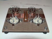
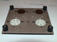
Here's how I do it:
Attachments
jlsem said:
Here's how I do it:
Looks great
I've just try to glue with bostik two boards, bakelite and fiberglass. It looks very good
For the screw I put in the holes a rubber fairleads so there's no mechanical connection between screw and board
Mark
mark_titano said:
@ pedroskova: noise is surely caused by a gnd loop...I'll rebuild the circuit next week ;-)
.Anyhow, shielding the input signal cable, the noise is gone down a lot.
Hi, Mark
Great to know you are still working on the CCS one. Look forward to seeing your next post.
JueiC
jueic said:
Hi, Mark
Great to know you are still working on the CCS one. Look forward to seeing your next post.
JueiC
Hi JueiC, I'll go through it. I've just bought components to make the modified c4s posted by pedroskova. I opened this discussion also to know how I can built it in a better way
I'm looking for resources regarding pcb design to make a good pcb for the ccs...I'd like to post it on line to help who wants to do it.I have to say that what I've found is nothing interesting

I've posted some examples in the 5687 3Ds... none said anything.
Maybe I have to open another 3ds asking for layout advises. Mah
Mark
I belive such a stickied topic would have merit
Chassis:
Non-ferrous metals, such as aluminum, copper and brass:
- very low hum pickup due to their LF shielding abilities as well as non-conductive to magnetic fields
- easy to work with. Bend by hand, punch with simple tools or scrollsaw
- raw aluminum and brass cheap to obtain as "door kickplates"
- bring magnet - not all metal sold as copper and brass *is* copper or brass, but plated potmetal from a third-world nation
Ferrous materials (if a magnet sticks to it....):
- essential for RF design
- physically rugged
- inexpensive compared to non-ferrous
- most variety
Baking utensils (inexpensive compared to chassis!!!!):
- square/rectangular aluminum cake pans
- commercial bakeware/steamtable ware (stainless)
- European bakeware (tin) is solderable and thick (3/16" to 1/4")
- usually much purer alloy (virgin metal, rarely recycled)
- available everywere
I'm quite taken with Morgan Jones's suggestion of making a frame with aluminum channel stock and making the top plate from perfed aluminum. Enough so that I bought a non-ferrous metal cutting blade for my miter saw and have some perf aluminum on order. Shielding and ventilation all in one- it's one of those "D'oh!" ideas that seems obvious in retrospect...
mark_titano said:
I've just bought components to make the modified c4s posted by pedroskova. I opened this discussion also to know how I can built it in a better way
I have to say that what I've found is nothing interesting
Hi Mark - be sure to read the thread that I posted with the schematic. IRC, Gary Pimm made a suggestion or two to improve on it.
pedroskova said:
Hi Mark - be sure to read the thread that I posted with the schematic. IRC, Gary Pimm made a suggestion or two to improve on it.
Ok thankyou. Gary give me his blessing to use, in his bbmccs, the ifr830 instead the 820. I'll try this solution too.
Thankyou again
Mark
- Status
- This old topic is closed. If you want to reopen this topic, contact a moderator using the "Report Post" button.
- Home
- Amplifiers
- Tubes / Valves
- Tutorial: building techniques