The emphasis is on not connecting the transformer secondary to (B+) ground, and not connecting the filament's raw dc supply to (B+) ground. Of course it routed to (B+)-ground right at the filament terminals - a star-connected wire to the cathode resistor, or to ground (for fixed bias).
The aim is to ensure that no current flows from the filament supply into the cathode/gnd/B+ circuit.
No dc, because there's only one wire between Ground and the filament terminals.
No ac either (i.e. noise), up to very high frequencies, because the regulator blocks this noise path. This blocking is done by having transistor stages on both sides of the filament, with the lowest capacitance leakage possible, consistent with the power they must handle. (This is the reason that my regulator kits are shipped with different pass transistors for different DHTs)
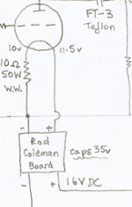
I wonder if it's just a drawing error though. Andy seems to connect the CCS input to ground. He shows four connections on Rod's board, two connections + and - 16V DC at the bottom which I would assume is +16V DC on +, and ground/0V on -. There's also + and - at the top of Andy's drawing of the board, which, according to Rod's schematic: + is the gyrator output, and - is the CCS input.
Attachments
I wonder if it's just a drawing error though. Andy seems to connect the CCS input to ground. He shows four connections on Rod's board, two connections + and - 16V DC at the bottom which I would assume is +16V DC on +, and ground/0V on -. There's also + and - at the top of Andy's drawing of the board, which, according to Rod's schematic: + is the gyrator output, and - is the CCS input.
Iko, I believe that Andy's drawing is correct.
This is one reason I have laboured the observation that the filament supply must be floating, except for the cathode current return.
In this drawing, particular care must be taken not to confuse the 16V- and ground: - these do not join.
Having established that clearly, it is apparent that you can now connect the gyrator ("+"), or CCS ("-") as the cathode terminal. The filament supply does not care, because there should be not be any current flow from the filament supply to the "Ground" - the B+ Ground, that is.
The chief difference in either case is only the shift in bias.
apropos bias, the effective bias voltage shifts positive when you use the FIL+ terminal as the cathode return terminal. The value of the shift equals the filament voltage - compared with connecting the other way around.
When trying each direction in turn, fixed bias amps should be adjusted by the value of the filament voltage. so to go from FIL - to FIL+ return, a 300B (Vfil = 5V) would need to adjusted from -70V, say, to -75V.
R Core transformers
It has been brought up here a few times that high quality split bobbin transformers are important to lower the coupling capacitance between primary and secondary windings. It seems that R Core transformers also have split primaries and secondary’s. Has anyone used those and do they have other drawbacks?
Peter
An externally hosted image should be here but it was not working when we last tested it.
Last edited:
Big advantage of the R-core is probably the ability to mount it in the same chassis as the signal parts/tubes. The stray field emission should be small. A toroid can do the same, but the Toroid's inter-winding capacitances reach almost the nF level, and allow mains-borne noise right into your circuit. Please don't use these in a filament supply!
The R-core should have even lower inter-winding capacitance than a split-bobbin (which can achieve 50pF at normal filament current applications - eg. 9V 50VA).
If anyone has measured the R-core inter-winding capacitance, I would be glad to see it posted here!
.
The R-core should have even lower inter-winding capacitance than a split-bobbin (which can achieve 50pF at normal filament current applications - eg. 9V 50VA).
If anyone has measured the R-core inter-winding capacitance, I would be glad to see it posted here!
.
split-bobbin?
Hi Rod, could you please explain (or draw) what split bobbin transformer topology looks like? Is it two separate transformers in 1 frame? Is it only applicable to a centre-tapped secondary? I am having a hard time understanding what it means and I'm sure others would benefit from your knowledge in this respect.
BTW, I tried to email you a week or two back with some questions, but was unable to get hold of you on the address you mailed me from.
regards,
William.
Last edited:
Hi Rod, could you please explain (or draw) what split bobbin transformer topology looks like? I am having a hard time understanding what it means and I'm sure others would benefit from your knowledge in this respect.
BTW, I tried to email you a week or two back with some questions, but was unable to get hold of you on the address you mailed me from.
regards,
William.
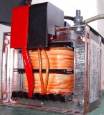
Hi William - Here's a photo of a nice HT trafo with split bobbin. See how the black moulded bobbin is split horizontally, with the whole of the mains-primary windings in the top section, and a pair of secondary windings in the lower section.
With this construction, the capacitance is formed chiefly by the proximity of the bottom of the top section - vs. - the top of the bottom section.
with this 150VA 370V trafo, the interwinding capacitance is below 100pF; filament trafos made this way show about 50pF.
In contrast, the nasty way of making an EI trafo is to wind the primary on a single-section bobbin, then some insulation, and then the secondary is wound directly on top. This gives much worse capacitive leakage, and some of this can still reach your filaments - despite the fact that the new regulators reject more noise than any other solution I have looked into...
Please just click on my username here to send some email.... please include a preferred return address.
Attachments
Another way to make your raw dc supply very quiet....
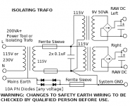
An isolating trafo will allow you to use a toroidal trafo, or other type with high noise coupling and still have the quietest possible solution.
Surplus power tool transformer, or units salvaged from industrial control panels are a good source of these.
Notice also, that my drawing shows the safety earth decoupled (ac-wise) from the chassis. Do not attempt this arrangement unless you are CERTAIN of what you are doing, or have it inspected by a competent person BEFORE switching-ON .
Sadly, the safety earth is often a serious source of noise.
RF-decoupled Earth provides a barrier against safety-earth noise creeping in and spoiling your hard work from buffering the mains Line/Neutral. The diodes must be 10A (or of such a rating as to be sure to blow the mains fuse before the diodes are themselves overloaded). Their leakage capacitance allows some HF noise through still, so a clip-on ferrite (see the Wuerth catalogue) is also recommended.
It's worth exploring all kinds of refinements like this, since IME, a top-flight DHT-powered audio system is sensitive to to minutest encroachment of noise, not least at the filaments.
Attachments
The Filament regulators give a layer of noise isolation on both sides of the filament. The performance of the buffers depends on the leakage capacitance of the pass transistors: 35 .. 100pF in the case of my design, depending on the model. Low capacitance means noise protection up to higher frequencies, and this is important, because HF/RF noise is usually modulated (in amplitude, or in phase), and parts of an amp can effectively demodulate the noise - think of the noise as RF carrier, and the AM or FM modulation being allowed in through the leakage capacitance... The RF can enter a power stage, and leak through to the low-level stages, too.
pF-level of leakage is very hard to improve, except by adding another layer of isolation, either by using better transformers, or finding a way to block noise between the transformers and the regulator. Noise blocking that is effective into the range of modern-day noise sources (mains-carried, and rectifier recovery) is much more difficult than it appears at first blush, so attention to the transformers is always worth trying.
I use the isolating transformer myself, and believe it to be worth the trouble, even for 300B output stage.
You can hide the Iso-trafo in a remote corner, and run mains leads to the amp's filament supply.
On the other hand, if you have cheap filament trafos, and the rest of your gear is pretty good, I suspect there's a very good chance of you hearing the improvement, if you add either isolating trafo, or better trafo, especially if you can get one with an ES-screen.
Rod - what are your opinions on mains filters? I have a huge and heavy one - probably a massive toroid inside - which I don't really use. I couldn't hear too much difference. Mind - my 26 filament supply which does actually use toroids also has the benefits of a choke input supply which presumably strangles some of the sins of the toroid!
andy
andy
I avoid industrial mains filters, because although series impedance is good against noise, in this position it's in series with the cap recharge current - and this causes unpredictable results, often bad ones....
chokes are better used in the smoothed dc portion of the circuit, where their inductance is not subject to fast-rising current steps. Step currents can excite inductive parts into resonance, which is very unhelpful.
Also, note that the (secondary-winding) peak current into the rectifiers is 4 to 7 times the value of the dc current, making inductor/filter choice very difficult.
When the dc is rectified and smoothed by the first cap, adding inductance after this is usually beneficial.
Additionally, when the inductance is high, even at the rectifier-first cap interface you win by adding a choke because you make a choke-input filter, and the conduction angle is improved.
In between, fast current steps into small inductance run the risk of unpredictable behaviour, and this is not helpful. It looks too much like a radio transmitter's output stage, and this may indeed be the outcome (unwanted transmitting!)
- Home
- Amplifiers
- Tubes / Valves
- New DHT heater