Glad you are enjoying them, Martin.
Yes, current-drive filament regulators will work well as a heater-current bias with IDHTs, too.
Actually, I used this method with EF80s before ever trying it with DHTs, and it worked very well - no need for electrolytic cathode bypass caps, when you can do it this way. The regulator must be very low noise, of course - LM317s are marginal, and sometimes audibly noisy.
Please try it, with confidence.
Hi Jaap,
At 2,5A dc the rms current in both branches of the bridge-rectifier will be about 4,8A. So that's 2,4A per branch.
The 1N5822 can withstand an average current of 3A, but should be derated by 20% for capacitor loads - but it should be just about OK if the diodes are mounted on some PCB material, and well-ventilated.
If the case temperature of any diode exceeds about 80 deg C, add some kind of metal heatsinking (clipped in place)
Thanks for your excellent support Rod. It's a pleasure working with your boards (and reading your brilliant instructions now that I've found them
") ).
). According to the (long wired) DMM the regulator leaves 1mV ripple when feeded 0,69Vac from a single 6.800uF. Let's see if that can be pushed behind the comma with these Siemens Sikorel LL 12.000uF/35V in C-R-C.
An externally hosted image should be here but it was not working when we last tested it.
OK, this is what's on the table:
No snubber on secondary, bridge with 1N5822 Schottkies:
No snubber on secondary, bridge with MBR1045 Schottkies:
Not much difference, as expected
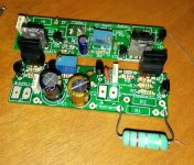
The advantage of the 10A diodes is that they can be screwed to a heatsink,
as they become quite hot, passing 2,5A to the 2A3.
Full resolution (with 47R+100nF snubber), 15cm wires (twisted) between regulator and 2A3. Measured at the valve socket.
Setup with air cooling:
An externally hosted image should be here but it was not working when we last tested it.
No snubber on secondary, bridge with 1N5822 Schottkies:
An externally hosted image should be here but it was not working when we last tested it.
No snubber on secondary, bridge with MBR1045 Schottkies:
An externally hosted image should be here but it was not working when we last tested it.
Not much difference, as expected
The advantage of the 10A diodes is that they can be screwed to a heatsink,
as they become quite hot, passing 2,5A to the 2A3.
Full resolution (with 47R+100nF snubber), 15cm wires (twisted) between regulator and 2A3. Measured at the valve socket.
An externally hosted image should be here but it was not working when we last tested it.
Setup with air cooling:
An externally hosted image should be here but it was not working when we last tested it.
130mV to regulator and 1,2mV out? You won't easily beat that, I dare you
I've got 4A CM coils to replace those .22's perhaps that will make the shape of the AC more symmetrical.
Rod -if you might read this- what's your opinion on further smoothing the power to the regulator? Can you comment on the shape of the last picture... it looks like the signal is changing in time what would suggest a resonance. Is that last pico Farad bypass before the reg worth investigating?
Hmm, it seems the residue has nothing to do with the regulator.
The left side shows an unpowered 2A3, the right powered.
Stray pickup or worn out PS in my 1974 scope?
The left side shows an unpowered 2A3, the right powered.
Stray pickup or worn out PS in my 1974 scope?
An externally hosted image should be here but it was not working when we last tested it.
Hi Disco,
As Bas wrote, 15000uF is not too much.
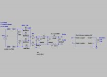
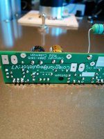
This is my 2.5A heater PSU (paralleled 801a in my breadboarded PSE).
This is r-C-L-C-CMC-C style raw PSU. Power transformer is 12V/5A, graetz is built with MBR1045 diodes.
In my #691 post this is the panel in middle, and above this the -two- 5mH/0.1Ohm 4A choke.
Without large capacitors and choke I have audible hum.
As Bas wrote, 15000uF is not too much.
This is my 2.5A heater PSU (paralleled 801a in my breadboarded PSE).
This is r-C-L-C-CMC-C style raw PSU. Power transformer is 12V/5A, graetz is built with MBR1045 diodes.
In my #691 post this is the panel in middle, and above this the -two- 5mH/0.1Ohm 4A choke.
Without large capacitors and choke I have audible hum.
Attachments
Hmm, it seems the residue has nothing to do with the regulator.
The left side shows an unpowered 2A3, the right powered.
Stray pickup or worn out PS in my 1974 scope?
mV is usually stray. Very regular tho, like an oscillation. Lesser loop areas, shorten cables, use good probes, move coils away.
Hmm, it seems the residue has nothing to do with the regulator.
The left side shows an unpowered 2A3, the right powered.
Stray pickup or worn out PS in my 1974 scope?
Hi Jaap,
Yes, this is just pickup from HF radio stations. It's quite normal, and has as much to do with the instrument as the wiring.
If you measure the noise residual with the Mic input of a good sound card, and look at the audio FFT - it will be nearer to microvolts.
Hi Disco,
As Bas wrote, 15000uF is not too much.
This is my 2.5A heater PSU (paralleled 801a in my breadboarded PSE).
This is r-C-L-C-CMC-C style raw PSU. Power transformer is 12V/5A, graetz is built with MBR1045 diodes.
In my #691 post this is the panel in middle, and above this the -two- 5mH/0.1Ohm 4A choke.
Without large capacitors and choke I have audible hum.
There's space underneath the deck, so I'll have a test or two later.
Some tubes are bastards to silence (26 comes to mind) wile other are sheep.
I don't expect to hear hum, even with 130mV ripple to the reg.
Thanks. Good to know...Thanks! The V7 gets better as the caps settle in (10 hours or so, powered on)
Hi Jaap, Yes, the V4 has a raised Q2; in V7 it's lowered - both cases to optimise the temperature tracking.
As for R1/2 - you could try a Mills MRA5 (nonInductive) - it's possible that higher quality parts are audible. At 1.2A+ the excess current-noise may be lower, though I can't measure any broadband noise from the regulator with standard wirewounds (uA level noisefloor).
As for R1/2 - you could try a Mills MRA5 (nonInductive) - it's possible that higher quality parts are audible. At 1.2A+ the excess current-noise may be lower, though I can't measure any broadband noise from the regulator with standard wirewounds (uA level noisefloor).
Hallo Jaap,Bas, do you experiment with R1/R2 resistors? Some nice wirewounds perhaps?
No I have not (yet). Not sure I want to
...its an expensive hobby as it is. I've started thinking about Mills MRA5.
you could try a Mills MRA5
5W MRA5??? Even at 1.25A this small (
) Mills will turn dark brown. I use this resistors in max. 1.5-2W dissipation positions.
I tried 5W noname (russian and chinese) wirewounds, hungarian 16W Remix wirewound, Mills (MRA5, MRA12), Welwyn (W23 - 10W, W24 -14W) resistors.
The previous ones has very mediocre sound, 5W is too small, large Mills and Welwyn for me is perfect.
I think 12-14W resistor is in the safe side, especially when you use 2-2.5A regulator.
Finally I use in all R.C. regulators 14W Welwyn W24 (thermal resistance is 22 Celsius/Watt, up to 200 Celsius grade) resistors.
- Home
- Amplifiers
- Tubes / Valves
- New DHT heater