Hi,
I use a 10M90S (or 10M45S, similar issue) as CCS from kathode to V- (6SN7 driver stage). The CSS is mounted about 8 cm away from the tube.
With certain settings (CSS is regulated with potentiometer) the CCS starts oscillating. What do you use to prevent this kind of oscillation? Ferrite beads, capacitor, shielded wiring?
Regards, Gerrit
How much DC voltage do you have across the 10M90S part?
If you use less than the required burden voltage across the 10M90S (or 10M45S), the reactive component of the CCS changes a lot.
6SN7 tubes are capable of RF oscillations, especially when they are connected to active device changing reactances.
Is there a 1k grid stopper directly connected to the 6SN7 socket grid pin?
Is this a cathode coupled phase splitter?
Please post a schematic, with voltages.
I had a parallel 12AY7, with cathodes directly connected, grids with individual 1k grid stoppers and the other ends connected together to the single signal source, and the plates directly connected. The parallel plates connected to a 10M90S (plate load).
Sometimes they oscillated.
I ended up connecting each plate to individual 1k 'plate stopper' resistors, and from there to the CCS.
With the new plate load 500 Ohms in series with the 10M90S, the output signal amplitude at the CCS is almost as large (there is an extremely low signal drop in the 1k resistors).
RF oscillations happen.
Fix them.
Happy Listening!
Last edited:
Hi 6a3sUMMER,
I use the CCS from Cathode (just a few volts DC) to a negative voltage of 50 Volt.
I use 1K grid stoppers directly on the grid.
It’s a balanced amplifier, not a phase splitter.
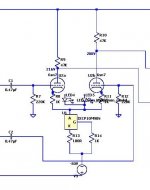
I don’t have a diagram available on my iPad right now, but I will try to add one tomorrow.
I tried small resistors from each cathode to the CCS as well.
I cannot put the CCS any closer to the tube, so there is some wiring necessary.
Regards, Gerrit
I use the CCS from Cathode (just a few volts DC) to a negative voltage of 50 Volt.
I use 1K grid stoppers directly on the grid.
It’s a balanced amplifier, not a phase splitter.
I don’t have a diagram available on my iPad right now, but I will try to add one tomorrow.
I tried small resistors from each cathode to the CCS as well.
I cannot put the CCS any closer to the tube, so there is some wiring necessary.
Regards, Gerrit
With 1k cathode resistor and CCS you have mixed bias.
The CCS half current flows through the 1k resistor and produces negative voltage on cathode (if the current is enough large).
The 10M90 with 100R bias resistor produces 23.3mA current, IMO is too much.
With 300R the current is 10.2mA.
The CCS half current flows through the 1k resistor and produces negative voltage on cathode (if the current is enough large).
The 10M90 with 100R bias resistor produces 23.3mA current, IMO is too much.
With 300R the current is 10.2mA.
Try a 10 ohm series resistor right at the drain of the 10M90S.
Adding a ferrite bead right on the drain lead is not a bad idea.
How close is that 1K resistor to the gate lead?
Decoupling on the -50V rail near the CCS?
Can you provide a picture and also measurement of oscillation frequency?
Adding a ferrite bead right on the drain lead is not a bad idea.
How close is that 1K resistor to the gate lead?
Decoupling on the -50V rail near the CCS?
Can you provide a picture and also measurement of oscillation frequency?
Hi,
The CCS is used to setup the tube for best audio, low THD for the required output. I measure with a spectrum analyser, oscilloscope and ears.
Each tube differs somewhat, so I made a variable CCS.
The LED is an alternative to the cathode resistor. It’s either the cathode resistor or the LED that’s connected to the CCS. I’m still not 100% sure what is best.
The gate resistor is mounted on the 10M90S. I shortened the gate lead as much as possible.
I will check on the -50V decoupling again.
I’m not only referring to my current built, but in general I see the 10M90S oscillating a lot in all my testing. I’m sure I will not be the only person seeing this. In the amplifier I’m working on right now I have to build the CCS again, so I want to try to do it right from the beginning. Adding components later is not a good thing and becomes messy. I’m not using a PCB, but point to point wiring.
Regards, Gerrit
Gerrit,
I have used 10M45S and 10M90S for the same purposes.
I selected 10M90S for safety margin when using as Anode load, since I had managed to blow a few 10M45S with power on transients, and no matter what work around I used (many found here) nothing solved the issue.
However, I was disappointed with 10M90S and have since managed to blow one of those too - goodness knows HOW, with a 300V HT supply.
I did not find oscillation, but the 10M90 wsnt working long enough for me to investigate well.
So I assume they MUST have been oscillating and that caused their death.
Now I won't use anything but DN2540, LND150, or HV BJTs
The CCS is used to setup the tube for best audio
--------------------------------------
Best audio results when the circuit parameters are set correctly, not the other way round. What frequency is the oscillation?
If the CCS is set for 10 mA each triode will have to pass ~5 mA. Drop across the 47K plate resisters is then 235V. The B+ would need to be 235 + 216, or 451V. What is the plate voltage supply at that point?
Setting the CCS to 20 mA is an impossible situation in this amp.
The CCS bias & gate resister need to be non-inductive.The gate resister, small as physically possible, I've used 1/8 watt. CC resisters work well.
Using diodes as biasing elements in the cathode circuit has questionable benefits. That adds yet another non-linear device into the audio path.")
--------------------------------------
Best audio results when the circuit parameters are set correctly, not the other way round. What frequency is the oscillation?
If the CCS is set for 10 mA each triode will have to pass ~5 mA. Drop across the 47K plate resisters is then 235V. The B+ would need to be 235 + 216, or 451V. What is the plate voltage supply at that point?
Setting the CCS to 20 mA is an impossible situation in this amp.
The CCS bias & gate resister need to be non-inductive.The gate resister, small as physically possible, I've used 1/8 watt. CC resisters work well.
Using diodes as biasing elements in the cathode circuit has questionable benefits. That adds yet another non-linear device into the audio path.
Hi,
I’ve not tried the DN2540 yet, as they are out of stock everywhere. I just checked again today and all stocks are down to zero. Only Ebay/Aliexpress sales, and I have seen too many fraud with imitation components. That is a no go area for me.
So far all my 10M90S have survived my testing (not all 10M45s though).
Regards, Gerrit
Hi John,
I know. I noticed some differences in the 3-4-5-6 mA area (per tube half). B+ is 400 VDC (MOSFET regulated and stable within 1V). I tend to use around 4 to 5 mA as optimum.
I don’t know the exact frequency of the oscillations, but some were in the hundreds of Khz. range, causing strange buzz and noise sounds in the audio output.
Regards, Gerrit
- Home
- Amplifiers
- Tubes / Valves
- 10M90S oscillating