Ha! I didn’t but since there’s no DC path, due to the coupling caps it shouldn’t matter, DC can’t pass the coupling caps either side of the ECC99 so its DC balance point is not affected by what happens behind or in front of it.
Yes but as you correctly pointed out it may be a problem with oscillation and isolating the EC99 should change the situation quite a bit.
I would consider the cascaded setup you have now as quite at risk for oscillations.
@john,
Please refer to post #83, thanks!
https://www.diyaudio.com/forums/tub...ax7-ltp-stupid-performance-9.html#post6860901
Please refer to post #83, thanks!
https://www.diyaudio.com/forums/tub...ax7-ltp-stupid-performance-9.html#post6860901
Cascode Amplifiers
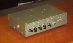
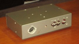
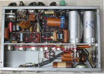
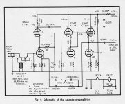
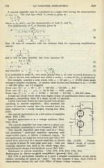
Just after the Earth cooled Vacuum Toob Cascode Amplifiers were common. There are three common ways to connect stacked triodes. The example taken from Audio magazine shews each of them. The first stage is a Cascode, the output signal is taken from the plate. So gain like a pentode but with a better triode noise figure. No partition noise of a pentode to get in the way. The 2nd stage is a version of the MU follower, the output signal is taken from the lower triode plate, although the upper cathode would have lower impedance. With a couple of minor mods the 3rd stage signal becomes a White CF. I built a copy of this preamp circa 1957 while working in a research lab. Like many other projects it is here on the shelf.
RF Cascode amps often went a step farther, the cathode was driven by the incoming signal rather than the grid, thus grounded grid. So works well in low Z RF circuits. And sometimes one step more, the signal from the lower triode was AC coupled to the top triode, no problems with H-K insulation for the top tube that way. Anyone who repaired the TVs from that era would be somewhat familiar with those circuits. But perhaps not, these circuits where often off limits due to the fragile nature of the RF adjustments.
Your 2-stage diff amp front end uses active common mode NFB in each stage. About a week after the Earth kooled tube amps were doing the same thing, although perhaps not as well. All covered in boring detail in the olde EE text books.
The circuits in posts 1, 2, 17, 45, 63, & 67 are Cascode, the others are not. Most of the others are better described as Cascade. Perhaps the thread needs a new title.")
Just after the Earth cooled Vacuum Toob Cascode Amplifiers were common. There are three common ways to connect stacked triodes. The example taken from Audio magazine shews each of them. The first stage is a Cascode, the output signal is taken from the plate. So gain like a pentode but with a better triode noise figure. No partition noise of a pentode to get in the way. The 2nd stage is a version of the MU follower, the output signal is taken from the lower triode plate, although the upper cathode would have lower impedance. With a couple of minor mods the 3rd stage signal becomes a White CF. I built a copy of this preamp circa 1957 while working in a research lab. Like many other projects it is here on the shelf.
RF Cascode amps often went a step farther, the cathode was driven by the incoming signal rather than the grid, thus grounded grid. So works well in low Z RF circuits. And sometimes one step more, the signal from the lower triode was AC coupled to the top triode, no problems with H-K insulation for the top tube that way. Anyone who repaired the TVs from that era would be somewhat familiar with those circuits. But perhaps not, these circuits where often off limits due to the fragile nature of the RF adjustments.
Your 2-stage diff amp front end uses active common mode NFB in each stage. About a week after the Earth kooled tube amps were doing the same thing, although perhaps not as well. All covered in boring detail in the olde EE text books.
The circuits in posts 1, 2, 17, 45, 63, & 67 are Cascode, the others are not. Most of the others are better described as Cascade. Perhaps the thread needs a new title.
Attachments
OK, got it. Did you try unhooking the NFB?
If the problem is still in the circuit, pull the KT88s,
run the 2-stage driver amp in isolation.
If balance is achieved you are on the way to a fix.
The amp is probably oscillating at RF. Need a wideband
scope & search probe to look.
If you have a suitable sheet of any kind of metal try connecting it with a very short lead to the amp common lead & placing it under your wood based amp. A ground plane may fix the problem.
Did you try unhooking the NFB?If the problem is still in the circuit, pull the KT88s,
run the 2-stage driver amp in isolation.
If balance is achieved you are on the way to a fix.
The amp is probably oscillating at RF. Need a wideband
scope & search probe to look.
If you have a suitable sheet of any kind of metal try connecting it with a very short lead to the amp common lead & placing it under your wood based amp. A ground plane may fix the problem.
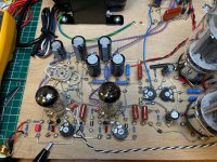
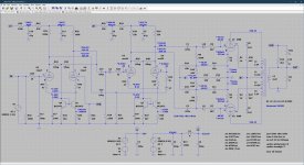
Alright, a few updates, removing the global feedback loop did reduce the negative grid voltage on the ECC99, so I moved the grid stopper resistors closer on the sockets and installed some ferrite beads, this reduced it further, but still not close to 0V. On the scope I couldn't see any oscillation, or it was so small it was buried in the noise. I then took baudouin0's suggestion to indeed make an explicit current mirror and also increased the feedback capacitor across the feedback resistor from 470pF to 1nF and reduced the grid resistors to 220K from 470K. This seems to have been most effective, there's still an inbalance at the anodes of the ECC99 though. Next thing to try is swapping inputs and outputs on the ECC99 to see whether the inbalance also moves, if not maybe someone peed on my piece of wood when it was still at the hardware store? The schematic has the actual measured voltages noted with a * alongside the simulated values.
Attachments
Last edited:
... there's still an unbalance at the anodes of the ECC99 though. Next thing to try is swapping inputs and outputs on the ECC99 to see whether the inbalance also moves ...
And it does, so this appears to be tube related, rather than circuit related, hence all 8 of the ECC99s I have here have the same unbalance. But just to approach this a bit more scientifically I'll go try some other tubes, ECC82 for example, as I need just one exception to disprove this theory.
And because I can't seem to edit my previous posts, here's the changes I made thusfar in a easier to read format:
- Moved all grid stopper resistors as close as possible to the pins on the sockets.
- Added ferrite beads in series with all grid stopper resistors.
- Changed the grid resistors of the ECC99 from 470K to 220K.
- Changed the current source to a current mirror.
- Added degeneration resistors, 47 Ohm, in the cathodes.
- Compensation C for the global loop changed from 470pF to 1nF.
I don't think its oscillation at least at VHF/UHF. Interesting if you simulate the grid imbalance you have you get exactly the plate imbalance you have. Still think its your wood! Could you post the .asc I am interested in you design.
Sure, as soon as I’m at work and behind my desk again I’ll send you the .asc.
I don't think its oscillation at least at VHF/UHF. Interesting if you simulate the grid imbalance you have you get exactly the plate imbalance you have. Still think its your wood! Could you post the .asc I am interested in you design.
@baudouin0,
Please see the contents of the attached zip file. In there you'll find two designs, one is the original cascode design I set out to prototype, the second is the current prototype. Would be interested to hear your comments, thanks!
Attachments
Alright, the unbalance is understood now and it was due to the wood I used as a basis to build the prototype on, apparently there's some current leaking somewhere, so I'll rebuild.
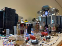
Finally some progres with the building
btw It depends on the wood, my teak has a very high insulation, even with 3kV no problem (kept dry for 40j)
But I had problems with plywood (birch) and no problem with mdf. In any case, I try to avoid "natural" fibers and anything that absorbs water (nylon), so even the teakwood i will not use.
If the wood is the problem why is the first stage not offset as well??? Perhaps the animals in the forest wet on only one part???
Yeah, plywood is obviously made from stacked layers of veneer rotated 90 degrees with every layer, I’m guessing some forest elf took a **** on some tree after a night of drinking elf ale who’s veneer made it into one of the inner layers? I’ll redo the prototype tomorrow using water resistant MDF, I checked a piece with my isolation resistance meter at 500 and 1000V, net resistance between two nails 5mm apart (that’s 0.19 Yankee units) was off scale, hence >5000MOhm.
Alright, the unbalance is understood now and it was due to the wood I used as a basis to build the prototype on, apparently there's some current leaking somewhere, so I'll rebuild.
Glad to hear you solved your issue!
That is the reason I use almost exclusively PCBs or very seldom conventional wiring with soldering strips.
Anton
- Home
- Amplifiers
- Tubes / Valves
- Cascoded 12AX7 LTP - Stupid good performance?