Let me check all the notes I took while playing with that circuit, I remember I did some tests on it. Play with the cascode reference voltage chasing best harmonics slope, not lowest thd.
I indeed tested also U440 to improve the pairing of the jfets: You can find 6n2p well matched from russian/ucrainian sellers.
Appreciate it, thanks! I already looked at the harmonics in the simulation, but will definitely do the same on the prototype.

Transistors are KSA992 sorry.
https://www.onsemi.com/pdf/datasheet/ksa992-d.pdf
https://www.onsemi.com/pdf/datasheet/ksa992-d.pdf
Last edited:
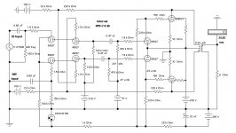
Cascode Front End Driving PP 6V6s in Class AB2
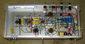
Something I dreamed up ~20 yrs ago. And all in hardware, actually completed.
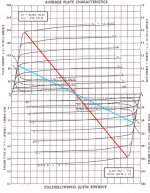
The PP 6V6s loadline is corrected for Class AB2 operation. CFs drive the 6V6 grids.
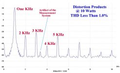
About 26W on a lab B+ supply. Trying internal NFB to the upper cascode grids, about 8db. And what is possible on a minimum PS, headroom, Etc.
And CFs driving the output grids. Still in working order here on the shelf.
Just another of several of experimental circuits I tried.")
Something I dreamed up ~20 yrs ago. And all in hardware, actually completed.
The PP 6V6s loadline is corrected for Class AB2 operation. CFs drive the 6V6 grids.
About 26W on a lab B+ supply. Trying internal NFB to the upper cascode grids, about 8db. And what is possible on a minimum PS, headroom, Etc.
And CFs driving the output grids. Still in working order here on the shelf.
Just another of several of experimental circuits I tried.
Attachments
What does the feedback to the top of the grid cascade do.
You can think of the upper cascode grids as being equivalent to a pentode screen, easy then to see how the feedback works (sort of like ultralinear). I've got a similar work-in-progress that unfortunately hasn't quite made it to the working stage yet.
As stated feedback can be applied to the top tube in much the same manner as one would apply feedback to the screen grid of a pentode. Cross coupled feedback in a push pull amp tends to reduce the odd order harmonics caused by imbalance as it tends to force better balance.
I also have several works in progress using these concepts. Here is one that made it to the working amp stage over three years ago. It does not use cross coupled feedback because my output stage technology does not invert the signal. This amp uses tiny tubes to make big power. How big? 50 WPC on an Antek toroid based supply, and 80 WPC at 3% THD on a regulated power supply.
Further work has wandered off in three distinctly different directions. Some involve the tech used in this output stage. The feedback goes directly to the control grid while the driving signal is fed through a P fet follower into the cathode. This allows for operating a sweep tube with its low voltage screen as a triode.
Attachments
The idea for that NFB to the upper grid of the cascode was a result of a meeting I'd had some time ago with Bill Perkins of PEARL HIFI. Bill at that time was an extremely busy guy, he had many projects in progress. One of those was a rather exotic vacuum tube HIFI amp. One of the internal NFB connexions went back to the screens of the tubes in the front end.
That circuit sat in the back of my mind for some time, I realized that without a tertiary winding on the OPT that whatever NFB could be applied would have to drive the screen resistance rs. thru a resister.
In another piece of recent work I've found rs to be in the range of 30-50K for common voltage amplifiers pentodes. But we would never see that published.
So why not a cascode, input to the top grids has no such limitation. Proof of Concept was one of the objectives of this amplifier build. In this case DC coupling from the output plates creates a minor problem in getting the DC level to the upper grids correct.
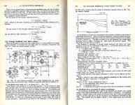
There is an example of NFB to the screen of the amp front end in RDH4.
That circuit sat in the back of my mind for some time, I realized that without a tertiary winding on the OPT that whatever NFB could be applied would have to drive the screen resistance rs. thru a resister.
In another piece of recent work I've found rs to be in the range of 30-50K for common voltage amplifiers pentodes. But we would never see that published.
So why not a cascode, input to the top grids has no such limitation. Proof of Concept was one of the objectives of this amplifier build. In this case DC coupling from the output plates creates a minor problem in getting the DC level to the upper grids correct.
There is an example of NFB to the screen of the amp front end in RDH4.
Attachments
Jan E. Veiset had a P-P design years ago with UL N Fdbks to the driver screen grids. By adjusting the Fdbk resistors, he was able to get the screens to operate at a fixed %V of the driver plate Vs. This then caused the screen grids to draw a constant fraction of the driver plate current, making them look like fixed resistances. I tried this on the curve tracer once and it works. So a Mosfet follower is not needed in that case to drive the screen grids. But you are limited to a specific Fdbk amount. One should be able to adjust the distortion profile by adjusting the N Fdbk amount slightly around that resistive point, since the screen resistance will start to vary some, depending on which side of the neutral point (constant %Vp) it is adjusted.
Last edited:
Thank you all, I indeed tried the ultralinear cascode as shown here ( It's About Time & Ultra-Linear Line Stages ) on the phase splitter of the amp I linked before, but it seemed not so effective, or at least that was the impression by ears and on simulations (no measurements).
I have never tried to bring back feedback from output tubes' anodes back to driver's "screens" (actually top 12AX7s' grids) and it could be a new test on that circuit. Thanks everyone!
I have never tried to bring back feedback from output tubes' anodes back to driver's "screens" (actually top 12AX7s' grids) and it could be a new test on that circuit. Thanks everyone!
Jan E. Veiset had a P-P design years ago with UL N Fdbks to the driver screen grids. By adjusting the Fdbk resistors, he was able to get the screens to operate at a fixed %V of the driver plate Vs. This then caused the screen grids to draw a constant fraction of the driver plate current, making them look like fixed resistances.
Thank you for this info smoking-amp, can you please give some link to this amp? I've only found this thread ( Jan E Veiset Mini EL84 pp ) but there's nothing juicy inside.
Understand now that the top grid voltage will act as a pseudo screen as the plat curves for the bottom 12ax7 are not flat. I was was thinking of the JFET bottom where this would have little effect.
Is there much to choose between say a 12ax7 cascade and a 6ej7 pentode. I have used the latter as LTP and you can operate with lower plated resistors and still get the gain.
Is there much to choose between say a 12ax7 cascade and a 6ej7 pentode. I have used the latter as LTP and you can operate with lower plated resistors and still get the gain.
Old ham radio guys will look at these things and say "oscillator".
Old ham radio guys who still build tube audio amps will look at my output stage and say "grounded grid linear amplifier."
73, KB4LRE
I met with Bill Perkins of PEARL (Perkins Electronic Acoustic Research Lab) about 30 yrs ago when his amp with screen NFB was in the works. My effort using NFB to a differential cascode stage was in hardware & running about 18 yrs ago. And on both RAT & DIY several times since. Now we see several amps in vapor ware, nothing finished.
Attachments
Now we see several amps in vapor ware, nothing finished.
Some people here never get beyond the simulator stage. Others don't even get that far. My amp started as a few experiments and lots of sims, and lived there for about a year. I name my sims with the tube and the experiment number, when they get ready to jump to the real world, they get the name used here, CD_6DQ6_Amp_Build_It. The 6GF5 is a shrunken 6DQ6.
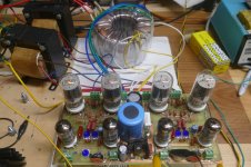
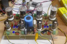
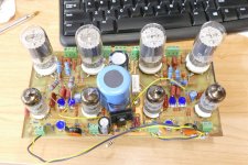
About 3 years ago the sims got turned into real hardware, though I have not yet built a chassis and or cabinet for it. This board, or a similar board with some minor revisions might wind up in a small rack mount chassis since it makes a studio monitor that really slaps the Yamaha NS-10M's around.
I have probably a dozen working amps that exist as PC boards. I hook them up and play them for a while, then swap the board for another. It saves lots of space that way. I have not built a complete amp on a chassis in about 7 years, but that's about to change.
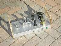
This one has seen rotation into one of my listening stations three or four times, and each time I find myself tinkering with it. The last time I spent some serious tinker time with it I tried 6 or 8 different driver tube types, hence the flying resistors in the output tube plate to driver tube screens feedback circuit. This picture was taken today of the board as it stands now. It is still a working amp and only needs 3 transformers to make sound.
Attachments
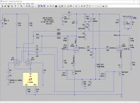
Thank you for the LTSpice file, George.
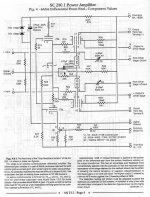
Is R16 a way to set the amount of feedback to driver's G2s?
I simulate alot before building, that's something that was true even when I was building instrument amplifiers only (before the world wide mess). So far I've built three Hi-Fi PP and one SE, but simulated way more than that.
Is R16 a way to set the amount of feedback to driver's G2s?
I simulate alot before building, that's something that was true even when I was building instrument amplifiers only (before the world wide mess). So far I've built three Hi-Fi PP and one SE, but simulated way more than that.
R16 does control the total amount of feedback. What this simulation will not tell you is that depending on the driver tube used the screen grid voltage can be WAY over the maximum Vg2 spec.
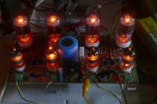
Since doing the sim and building the board, I have added resistors from each G2 to a low voltage source derived from the output tube's screen supply. This is the flying resistors and yellow wires seen in the picture.
There are several TV IF and video amplifier tubes that share the same pinout as the 6EJ7. I have tried every one, and they all work differently.
The board and the related UNSET works pretty good now, but I believe that there is still more performance to be had with these techniques, so the quest continues. I'm currently playing with cascodes that pair tubes and mosfets, both in the sim world, and with real parts.
- Home
- Amplifiers
- Tubes / Valves
- Cascoded 12AX7 LTP - Stupid good performance?