To follow up with the work I did on the big sister amp, the Boyuurange/Reison A50, a viewer had a new in the box A12 dropped shipped for me to review and possibly modify it etc.
I'm going to post this spoiler, it's a hot mess.
Massive distortion was visible on an analog scope and running a THD vs power sweep showed me that what I was seeing on the analog scope was reality. It goes into hard stop, square wave producing clipping at 1/2 the rated watts and crosses the 1% THD mark at 0.015W. It is making 6-7%+ distortion at 1W and it goes past 10% before 2W. The cheap little Nobsound 6P1 out of the box performs better than this. With my DIY >$20 mods it destroys the A12 at almost 1/2 the price.
I go into more detail in the review video and I'm hopeful in future videos I can find a resolution to whatever is causing these problems. It's a shame, as I had high hopes for this little amp, and it has what you would think it takes be a decent performer, 12AX7 driver into a SEUL EL34. But it's clearly a swing and a miss out of the box.
TL;DR at this point I would not recommend buying one of these with the expectation of goodness out of the box or just basic tube rolling. I'm sure this will be controversial, but the numbers don't lie.
Boyuurange Reisong A12: Technical Review - YouTube
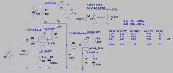
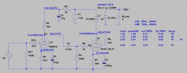
Basically it's the same as A10 (I bought cheap second hand one for rebuild, because of the box):
- crap OPT, which is rather 3k5 than 5k,
- crap OPT, with low inductance: high lower -3dB point,
- inappropriate EL34 operating point: with such low voltage (even in UL) this tube unable to produce more than few Watt with high distortion.
- crap OPT, which is rather 3k5 than 5k,
- crap OPT, with low inductance: high lower -3dB point,
- inappropriate EL34 operating point: with such low voltage (even in UL) this tube unable to produce more than few Watt with high distortion.
Should be interesting seeing how to fix this! I imagine using the EL34 in triode would work at a lower power level. One way to go.
You could add a small 12VA 24+24v transformer which would add 48v AC. Fairly small if there's room underneath. That's a fix I've used successfully.
You could add a small 12VA 24+24v transformer which would add 48v AC. Fairly small if there's room underneath. That's a fix I've used successfully.
Should be interesting seeing how to fix this! I imagine using the EL34 in triode would work at a lower power level. One way to go.
You could add a small 12VA 24+24v transformer which would add 48v AC. Fairly small if there's room underneath. That's a fix I've used successfully.
Sounds like it's probably useful as an anchor.
The question I have is - how does it leave the company manufacturing in this way? Surely they have a tested design and some semblance of quality testing of a manufacturer. (Retorical) Given it's come from fresh packed you shouldn't need to fix it - should be straight back to the manufacturer. Their waybill.
TL;DR at this point I would not recommend buying one of these with the expectation of goodness out of the box or just basic tube rolling. I'm sure this will be controversial, but the numbers don't lie.
Seems pretty damning!
Last edited:
I agree this amp should not be sold and likely were never tested. But someone sent me this amp to test, review and try to fix as thousands of these have been sold.
Here are my ideas to try based on easiest to most complicated: The driver stage doesn't seem to be the main problem,(it could use some help but...) so I plan to start with the output section.
The circuit/voltages seem to be made for a much lower watt output tube and they likely tossed in EL34 tubes to boost sales. It's only being run at slightly over 50%, so I want to just stuff a pair of 6V6G-S JJ tubes in (which will be running at 94%) and see what that does for it. I get that it won't change the power output, but I'm curious to see if running an SE amp "lazy" like this is part of the problem. My experiments have shown EL34 tubes like being run hard in an SE amp, and they are cheap so no big deal IMHO if their life is shortened. If this tube swap cleans up the distortion, and I can get even 2 fairly clean watts just doing a quick tube swap, that would be a win for many people that own these who aren't DIYers. Without more drastic changes, it's not going to put out more power anyway.
Next, change to full SS rectification. The 290V power transformer has no center tap, so they are doing bridge rectification by using SS diodes for the negative/ground and a cheap China tube for the positive side. I see nothing good happening from that (other than slower start up...) and I need more B+ if I'm gonna get the EL34 tubes to actually do something. I think I can probably get up to 40V more B+ adding some SS diodes and just leave that rectifier tube there for decoration.
I am very suspect of these "UL tap" output transformers. I plan to measure the winding ratios, but am also thinking to try strapping the EL34 as a triode and look at the results. If the massive distortion goes away, then I know the screen tap configuration is a problem. On my voltage tests, the screens have almost 5V more on them than the plate does. Possibly add some resistance to the screens might be part of the solution? They only have a 100 ohm resistor and I'm used to using more like a 1.2K resistor on UL taps. That might also be an easy thing to try, just swap a 1.2K resistor in one channel and see what happens.
Once I get this thing even slightly tamed, I have some other ideas on the driver, local feedback loop etc.
For whatever reason, I really enjoy trying to "fix" these popular models of china amplifiers, at least as much as is possible. I do wanna also thank the viewer who sent me this one to play with")
Here are my ideas to try based on easiest to most complicated: The driver stage doesn't seem to be the main problem,(it could use some help but...) so I plan to start with the output section.
The circuit/voltages seem to be made for a much lower watt output tube and they likely tossed in EL34 tubes to boost sales. It's only being run at slightly over 50%, so I want to just stuff a pair of 6V6G-S JJ tubes in (which will be running at 94%) and see what that does for it. I get that it won't change the power output, but I'm curious to see if running an SE amp "lazy" like this is part of the problem. My experiments have shown EL34 tubes like being run hard in an SE amp, and they are cheap so no big deal IMHO if their life is shortened. If this tube swap cleans up the distortion, and I can get even 2 fairly clean watts just doing a quick tube swap, that would be a win for many people that own these who aren't DIYers. Without more drastic changes, it's not going to put out more power anyway.
Next, change to full SS rectification. The 290V power transformer has no center tap, so they are doing bridge rectification by using SS diodes for the negative/ground and a cheap China tube for the positive side. I see nothing good happening from that (other than slower start up...) and I need more B+ if I'm gonna get the EL34 tubes to actually do something. I think I can probably get up to 40V more B+ adding some SS diodes and just leave that rectifier tube there for decoration.
I am very suspect of these "UL tap" output transformers. I plan to measure the winding ratios, but am also thinking to try strapping the EL34 as a triode and look at the results. If the massive distortion goes away, then I know the screen tap configuration is a problem. On my voltage tests, the screens have almost 5V more on them than the plate does. Possibly add some resistance to the screens might be part of the solution? They only have a 100 ohm resistor and I'm used to using more like a 1.2K resistor on UL taps. That might also be an easy thing to try, just swap a 1.2K resistor in one channel and see what happens.
Once I get this thing even slightly tamed, I have some other ideas on the driver, local feedback loop etc.
For whatever reason, I really enjoy trying to "fix" these popular models of china amplifiers, at least as much as is possible. I do wanna also thank the viewer who sent me this one to play with
- inappropriate EL34 operating point: with such low voltage (even in UL) this tube unable to produce more than few Watt with high distortion.
I think this could be the main issue, this looks like a 6V6G amp they put EL34 tubes into. That and possibly how they have the UL circuit setup.
Affordable tube amplifier + top notch build + rich sound = what's not to like? - YouTube
So Steve Guttenberg has so bad ears?!?
So Steve Guttenberg has so bad ears?!?
Affordable tube amplifier + top notch build + rich sound = what's not to like? - YouTube
So Steve Guttenberg has so bad ears?!?
Did Steve get a golden sample specific for reviewers to boost sales?
Next, change to full SS rectification. The 290V power transformer has no center tap, so they are doing bridge rectification by using SS diodes for the negative/ground and a cheap China tube for the positive side. I see nothing good happening from that (other than slower start up...)
A mixed ss and valve rectifier is actually OK and sounds fine. It's called a hybrid or Graetz bridge. The sound of the valve rectifier predominates. I've used this quite a lot and so have many others. A GZ34 will give you the lowest voltage drop if there's enough current to feed it.
A 6V6 output tube sounds like a very good idea. Smart thinking! Could sound nice, especially with a revised front end. You only need an input tube with a gain of 20 or so. In fact if you go all solid state you have a spare octal socket and you could stick a 6SN7 tube in there for the input. If you use the 9 pin input sockets you could use an EL84 in triode. With 6V6 output you have more gain in the amp already.
Ideas.....!
You only need an input tube with a gain of 20 or so. In fact if you go all solid state you have a spare octal socket and you could stick a 6SN7 tube in there for the input. If you use the 9 pin input sockets you could use an EL84 in triode. With 6V6 output you have more gain in the amp already.
Ideas.....!
17 amplification factor - 12BH7A
but it's a B9A base but would look nice.Affordable tube amplifier + top notch build + rich sound = what's not to like? - YouTube
So Steve Guttenberg has so bad ears?!?
Reisong A10 EL34 Hi-Fi Audio Stereo Tube Amplifier Single-end Class - A Review | Audio Science Review (ASR) Forum
It matches what I measured.
17 amplification factor - 12BH7A
It gain is enough up to 2.83V peek (2V RMS) input to drive low B+ EL34 amp.
Attachments
It gain is enough up to 2.83V peek (2V RMS) input to drive low B+ EL34 amp.
Longer plate:
Code:
**** 12BH7A_STR ** Advanced Grid Current **********************************
* Created on 08/24/2020 14:31 using paint_kit.jar 3.1
* [url=http://www.dmitrynizh.com/tubeparams_image.htm]Model Paint Tools: Trace Tube Parameters over Plate Curves, Interactively[/url]
* Plate Curves image file: 12bh7a-str.png
* Data source link:
*----------------------------------------------------------------------------------
.SUBCKT 12BH7A_STR 1 2 3 ; Plate Grid Cathode
+ PARAMS: CCG=2.9P  CGP=2.5P CCP=0.5P
+ MU=18.02 KG1=945.75 KP=185.4 KVB=1247.69 VCT=-0.6206 EX=1.181
+ VGOFF=-1.03 IGA=8.2E-4 IGB=0.162 IGC=6.624 IGEX=1.3
* Vp_MAX=500 Ip_MAX=16 Vg_step=2.5 Vg_start=5 Vg_count=12
* Rp=4000 Vg_ac=55 P_max=3.5 Vg_qui=-48 Vp_qui=300
* X_MIN=279 Y_MIN=106 X_SIZE=857 Y_SIZE=593 FSZ_X=1618 FSZ_Y=918 XYGrid=true
* showLoadLine=n showIp=y isDHT=n isPP=n isAsymPP=n showDissipLimit=y
* showIg1=y gridLevel2=y isInputSnapped=n
* XYProjections=n harmonicPlot=n dissipPlot=n
*----------------------------------------------------------------------------------
E1 7 0 VALUE={V(1,3)/KP*LOG(1+EXP(KP*(1/MU+(VCT+V(2,3))/SQRT(KVB+V(1,3)*V(1,3)))))}
RE1 7 0 1G  ; TO AVOID FLOATING NODES
G1 1 3 VALUE={(PWR(V(7),EX)+PWRS(V(7),EX))/KG1}
RCP 1 3 1G   ; TO AVOID FLOATING NODES
C1 2 3 {CCG} ; CATHODE-GRID
C2 2 1 {CGP} ; GRID=PLATE
C3 1 3 {CCP} ; CATHODE-PLATE
RE2 2 0 1G
EGC 8 0 VALUE={V(2,3)-VGOFF} ; POSITIVE GRID THRESHOLD
GG 2 3 VALUE={(IGA+IGB/(IGC+V(1,3)))*(MU/KG1)*(PWR(V(8),IGEX)+PWRS(V(8),IGEX))}
.ENDS
It sounds like it needs a good 22-24 tube with a bit of bite. If you want something a little more brutal there's the ECC99? happy for a larger input swing and lots of drive potential (typically 24mA OP, 60mA max).
Last edited:
Basically it's the same as A10 (I bought cheap second hand one for rebuild, because of the box):
- crap OPT, which is rather 3k5 than 5k,
- crap OPT, with low inductance: high lower -3dB point,
- inappropriate EL34 operating point: with such low voltage (even in UL) this tube unable to produce more than few Watt with high distortion.
Affordable tube amplifier + top notch build + rich sound = what's not to like? - YouTube
So Steve Guttenberg has so bad ears?!?
He also liked the A50 out of the box, it sounds horrible to my ears. Once the frontend was rebuilt to a cascode, it sounds reasonable but still not great.
I have no clue why he praises these China tube amps. I just tried to listen to this one and after 5 minutes I had to turn it off. Muddy and messy is how I would describe it.
What do you think of this guy review? I did watch couple of his videos in the past but no longer interested.
Class A sound on a budget! Reisong A12 tube integrated amp. - YouTube
Class A sound on a budget! Reisong A12 tube integrated amp. - YouTube
I'm wondering about converting it to 6B4G, or the excellent Russian version 6C4C which is cheap and plentiful. It would need another small 6v transformer and then the 6B4Gs could be run in AC with hum pots. This would probably be the best quality sound you'd get out of this. Could be really nice.
1. When using AC filament power on DHT tubes, the higher the rated filament voltage, the higher the Intermodulation will be (from 2 times the power mains frequency).
That intermodulation will appear on each and every musical instrument fundamental tone and instrument harmonic; singer's voice; and just plain sine wave test signals.
2.5V, 5V, 6.3V, 7.5V DHT with AC powered filaments, that intermodulation goes up as the filament voltage goes up.
Power that 6B4G 6.3V 1A filament with DC, not AC.
The problem with that and an existing amplifier power transformer, the requirement on the AC filament winding current driving diodes and capacitor filters, will be about 1.6 to 1.8 times the DC current. 1A DC will require 1.6A to 1.8A AC (a little higher than an EL34's 1.5A AC filament). Might need an additional filament transformer (with dual 6.3 windings to allow for both DHT tubes to each use individual self bias RC networks.
And, the bias voltage is higher on a 6B4G than on an EL34 on the same amp, for the same plate current. So the driver tube has to have more gain to output 2 times the bias voltage.
2. Better yet . . .
An easier modification might be to use a 6CK4 triode, 6BL7 dual triodes in parallel, or 6BX7 dual triodes in parallel.
Caution, the total glass envelope plate dissipation for these tubes is 12 Watts.
But these tubes can all use AC filaments, and all are equal to, or slightly less than the EL34 filament amperage.
And they all use octal sockets.
These tubes do not require high B+ voltage, another bonus.
Have fun modifying and listening!
All changes require other changes to get optimum performance from that amplifier.
Last edited:
Thanks for that. On second thoughts I'd use an outboard DC supply for the 6B4Gs and pirate a couple of the RCA plugs on the back to connect it.
I doubt very much that's what Stephe wants though - she wants an easy conversion with common parts for a typical user, and that's a valuable addition to her video series.
As you say there are other possibilities for output tubes. The 7591 is now available in a new JJ version and that could be an easy swap. Easy to drive with an EL84 in triode for instance because of its higher gain.
Vacuum Tube - 7591, JJ Electronics | Antique Electronic Supply
.
Last edited:
I doubt very much that's what Stephe wants though - she wants an easy conversion with common parts for a typical user, and that's a valuable addition to her video series.
I'm hopeful to swap a few resistors etc. around and at least make a reasonable amp out of this. I tossed a 250ohm cathode resistor in, 1/2 of the 500 ohm one it comes with, and it's starting to look promising. I'm probably going to do this again as "Basic mods", a few simple things that make a big improvement, and then a second set of more comprehensive ones that make it as good as possible without replacing the iron.
- Home
- Amplifiers
- Tubes / Valves
- Reisong A12 review