Another way of saying what other folks have already said (and better than me) is that leaving the common cathode resistor, in what looks like the middle stage of a DTNW amplifier config, unbypassed is usually the best design choice. Output stages with cathode bias benefit from individual cathode resistors, each with her own bypass cap, but the driving stage (normally) has a slightly different best design balance.
In either case, as jws has said, the capacitor is a liability.
All good fortune,
Chris
In either case, as jws has said, the capacitor is a liability.
All good fortune,
Chris
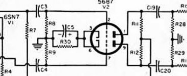
If it really is this amp then the cathode resistor is best shared and the bypass cap removed. This will ensure symmetry of the phase inverter circuit.I think it's this amplifier (see the triode connected version at the end of the article):
As Chris has pointed out, that's a typical Williamson front end. Usually that cathode resistor is unbypassed. I'm not sure why it is bypassed in this particular amp, perhaps to increase the gain to the output stage, or reduce distortion. But in most cases, for this type of design, you would not use a bypass cap in this position. But also do not use separate cathode resistors, the stage is designed to work with a single shared cathode resistor.
Some amplifiers on various threads of this forum DC couple from the driver to the output tubes.
If you are going to DC couple a driver to the output tubes, and you use a common cathode resistor for the cathodes, you better make sure that the driver triodes are exactly matched.
Otherwise, the output tube currents will be badly unmatched.
5,000 uMho output tubes and a 2V mismatch of the driver plate voltages causes a 10mA difference of the two output tubes current.
That is not good.
Ask your push pull output transformer if it likes that!
Last edited:
In the Chicago Standard 100 Watt Amplifier using CFB, by Kenneth Olsen (post #6 by PFL200), bottom of the 2nd page:
"Ten dB of gain reduction results in 20 dB of distortion reduction, or, in other words, the distortion is reduced by the square of the feedback factor."
I do see where CFB has a double effect of dist. reduction due to CFB directly and the inherent UL effect on the screen grid to cathode V. But why would this give more dist. reduction than gain reduction? Both effects separately give dist. reduction proportional to gain reduction. And together they would cause more gain reduction. Anyone have a clue to what/why is being claimed here?
Getting dist. reduction by square of gain reduction would be a pretty big deal. Never heard of it again.
Last edited:
I read thru the "Amplifiers and Superlatives" article (by Williamson and Walker) referenced by the Olson article, and I think I see where this "squared" dist. reduction idea originates, at least for Olson.
They are not counting the CFB gain reduction as being in the output stage, but rather gets passed back to the driver stage, and true. But Olson considers the dist. reductions (UL and CFB) to both be in the output stage. Hence the "something for nothing" concept there. Overall, including the driver, the dist. reduction IS proportional to overall gain reduction. But it does mean that the output tube stage does not have to supply all that extra gain, and can be more stable.
They are not counting the CFB gain reduction as being in the output stage, but rather gets passed back to the driver stage, and true. But Olson considers the dist. reductions (UL and CFB) to both be in the output stage. Hence the "something for nothing" concept there. Overall, including the driver, the dist. reduction IS proportional to overall gain reduction. But it does mean that the output tube stage does not have to supply all that extra gain, and can be more stable.
Smoking Amp is right on the money, nothing is free. Norman Crowhurst in his description of the McIntosh circuit makes the point the local CFB is 14 db, same as the gain reduction. I saw the same in the two Twin Coupled amps I built.
Boot Strapping eases the drive problem, that way a brute force driver such as in the subject cct is not required.")
Boot Strapping eases the drive problem, that way a brute force driver such as in the subject cct is not required.
Consider the Fundamental power level, versus the 2nd harmonic distortion level, and the 3rd harmonic distortion level.
A set of 3 race cars is on an oval track. The number of Miles traveled are counted.
One car drives at 100 MPH. Name that car Fundamental
One car drives at 200 MPH, 100 MPH faster relative to the Fundamental. Name that car 2nd Harmonic.
One car drives at 300 MPH, 200 MPH faster relative to the Fundamental. Name that car 3rd Harmonic.
The Fundamental car starts first. It travels for 1 Hour, circles the track, 100 Miles.
The 2nd harmonic car starts 1 hour late. It travels for 1 Hour, circles the track 200 Miles.
In the mean time, Fundamental has traveled 2 Hours, but 2nd Harmonic traveling for 1 Hour has caught up to the Fundamental, they both traveled 200 Miles.
The 3rd harmonic car starts last (3 Hours late). It travels for 1 Hour, circles the track 300 Miles.
In the mean time, Fundamental has traveled 3 Hours, but 3rd Harmonic traveling for 1 Hour has caught up to the Fundamental. They both traveled 300 Miles.
The car race illustrates an amplifier's:
2nd harmonic intercept,
and
3rd harmonic intercept
But in a real amplifier, it never actually reaches the intercept; it is too far above the linear power levels of the amplifier.
For an amplifier with signal levels that are lower power, in the "well behaved" region of the amplifier:
Increase the Fundamental by 10 dB.
The 2nd harmonic distortion will increase by 20dB, but the 2nd will only increase by 10 dB relative to the Fundamental. 20 dB - 10 dB = 10 dB relative.
Increase the Fundamental by 10 dB.
The 3rd harmonic distortion will increase by 30dB, but the 3rd will only increase by 20 dB relative to the Fundamental. 30 dB - 10 dB = 20 dB relative.
Remember that for a very large numbers of good amplifiers, when the signal power is very low, the 2nd harmonic distortion and 3rd harmonic distortion are very low Relative to the Fundamental.
If it is not this way, then that "First Watt" is not as good as it could be.
At moderate and high power levels, the harmonic distortion is larger relative to the Fundamental versus what it was relative to the amplifier's low power levels.
Perhaps this is hard to understand, but it has been accepted by a number of electronic industries; and has likely proven true in more cases than proven not true (at least approximately true).
Remember to think of the rates of increase of distortion as they are Relative to the Fundamental.
Listen and Enjoy the Music.
Have fun!
Your Mileage May Vary.
Last edited:
I found some info on the Chicago BO-14 CFB OT, 5K Ohm and 10% CFB by turns. A 16 Ohm secondary would be 5.6% turns. So I think these were wound with 4 extra (small wire) 16 Ohm secondaries for the CFB tertiary.
The Chicago BO-15 CFB OT info I found helps support % turns. 5626 Ohm full primary and 4552 Ohm plate only primary, and 11% CFB. 1.11 squared, times 4552 gives 5608. So 11% is by turns.
The Olsen article makes some comments about local plate Fdbks, that plate Fdbk does not properly sum with global Fdbk, like CFB does, hence wasting gain. I suspect this is purely a practical matter. Plate windings have more resistance, and typically the P-P halves are not matched for DC resistance or leakage L. A properly made OT could fix this. Using the UL taps for the Fdbks would probably work better on most UL type OTs, since that section would be more closely coupled to the secondary, just for UL purposes. The Chicago BO-14 and BO-15 OTs may have the CFB windings bifilar (or multi-filar) with the secondary as well.
Another problem, which CFB, plate Fdbks, or UL, -all- have is the primary winding resistance (times load current + magnetizing current) inserts a voltage which does not reflect output V. So local Fdbk is corrupted somewhat. Using a sense resistor in the output tube cathodes, fed back to the driver cathodes, could be used to cancel out primary winding resistance (by providing a small boost V to cancel the Rdrops). The cathode currents also include the magnetizing current, so that gets compensated also. The secondary does not include magnetizing current, so a resistance compensation scheme for secondary resistance would need to come off an output curent sensing R.
Last edited:
If you use high rp Pentodes or high rp Beam Power tubes, why worry about a 6k p-p primary that has DCRs to center tap that are unequal by 100 Ohms?
Example: 20k plates driving 100 Ohms DCR more on 1/2 primary than the other 1/2 primary.
If that really worries you, then put a 100 Ohm resistor in series from the plate to the lower DCR 1/2 primary.
'Bad' 20,100 versus 20,000; verus 'good' 20,100 and 20,100.
Now it is balanced!
If you use the same 6k p-p transformer, and drive it with 300B tubes, rp = 700 Ohms, now be sure to take care of it.
rp 700 Ohms, DCR difference 100 Ohms. Make both push and pull equal . . .
Be sure to use that 100 Ohm resistor in series from the plate to the lower DCR 1/2 primary.
Done!
When using the series 'DCR compensation resistor' . . .
Then if you use feedback from the output tube plates, then be sure to connect the feedback to the plates, not to the unequal DCR primary wires.
Pay attention to details, or live with whatever performance that you get.
Last edited:
For local N Fdbks from the plates, the series winding resistance error makes a difference to the Fdbk V quality, pentode or not. Adding some comp. resistance on one side will fix the inequality error as you said. Load current and magnetizing current are another matter, which needs negative resistance (equal to the primary side R) to fix.
Last edited:
A less than perfect transformer primary, with 2 different DCRs, and a series DCR correction resistor, may have other problems.
Un-equal end capacitances of the 2 primary 1/2s, and Un-equal leakage inductances of the two primary 1/2s to all the other windings.
A 100 Ohm series resistor to fix all the above problems may not be perfect.
Many things in life are not perfect.
Un-equal end capacitances of the 2 primary 1/2s, and Un-equal leakage inductances of the two primary 1/2s to all the other windings.
A 100 Ohm series resistor to fix all the above problems may not be perfect.
Many things in life are not perfect.
That's why using the UL taps for the N Fdbks should be a little better.
But in either case, a well designed, balanced, OT is best. Using a split bobbin and symmetrical wind is generally the easiest way.
For a brand X OT, one could compensate those small parasitic C and L discrepancies with some comp network on the cathode current sense resistors. Maybe not worth the effort.
Last edited:
A less than perfect transformer primary, with 2 different DCRs, and a series DCR correction resistor, may have other problems.
Un-equal end capacitances of the 2 primary 1/2s, and Un-equal leakage inductances of the two primary 1/2s to all the other windings.
A 100 Ohm series resistor to fix all the above problems may not be perfect.
Many things in life are not perfect.
The function of the designer is to correct the problems & put together a product at a reasonable selling price. Otherwise we would still be listening to Berliner's phonograph.
Think be used a disc..............or was it a drum?- Home
- Amplifiers
- Tubes / Valves
- Separating cathodes