jcalvarez,
You are fortunate to have built your first vacuum tube amplifier over 40 years ago.
In my example in Post # 17, when connecting tap 4 of the bias transformer to ground . . .
The B+ is +300V, and the bias is -50V (both referenced to ground, pin 4).
But since the ground (both power supply returns) are on tap 4, you do not get 350V B+ to ground.
Have it one way or the other, but not both.
I just wanted newbies to know that.
Just put the auxiliary supply in series with the positive side, not the ground/center tap. Then the bias tap works as expected.
Gee, you think?
Attachments
That was my first option, but I discarded it because I'm not sure about how good the insulation of the off-the-shelf transformer is.Gee, you think?
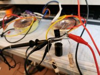
I think is time to plug the soldering iron and put together a proof of concept.
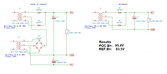
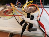
It works. Here are the results.
I understand that putting the additional supply on top would also works. However I think this arrangement has the following advantages:
1) No requirements for high voltage insulation of the booster transformer.
2) The B- can be used not only for bias, but for CCD B- too. You can take much more current than from the usual PT bias tap.
Attachments
Last edited:
But since the ground (both power supply returns) are on tap 4, you do not get 350V B+ to ground.
But they are not both on tap 4, and that is exactly why it does work ...
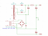
It becomes clearer when we put a cap to each of the rectifiers.
Now it is obvious that the positive outputs of each of the PSs add together.
And maybe that is the way I would have probably done it.
Anyway, it also works w/o the additional caps.
At first glance I thought the output would see some 50 Hz ripple from the booster rectifier, but that isn't the case, confirmed by sim as well as the boost.
Attachments
- Home
- Amplifiers
- Tubes / Valves
- Adding voltage to a PT