I have been thinking about how can one cheaply "add" more voltage to an existing PT, without going the SMPS route. I noticed there are plenty of cheap toroidal transformers around, for example a Vigortronix VTX-146-030-225 would add 50VAC/0.6A (£20) to a 300-0-300 PT. Is there anything wrong with the approach in the picture attached?
Attachments
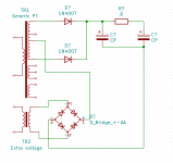
Yes, that'll work. Since the bridge diodes will conduct if the second transformer isn't powered, you could switch it off for lower B+. I actually did this with a radar transmitter some years ago.... "If you don't need the full 40 KW peak, just flip this breaker off and you'll have 25KW..." Used stacked supplies since the transformers were in stock, and we only built the one transmitter.
Yes, that'll work. Since the bridge diodes will conduct if the second transformer isn't powered, you could switch it off for lower B+. I actually did this with a radar transmitter some years ago.... "If you don't need the full 40 KW peak, just flip this breaker off and you'll have 25KW..." Used stacked supplies since the transformers were in stock, and we only built the one transmitter.
Thanks! I did not realise that powering off the extra transformer just takes it back to the original voltage, good catch!
Great candidate for a "Turbo" switch
")
Just be careful not to exceed the insulation's voltage rating of the top transformer (assuming ground is the negative side of the supply)
Don't forget fuses whatever scheme you use - separate ones for each primary, don't directly parallel them.
Thanks for the tip about the fuse. To be honest I would have used one common for both, after your comment I realise that we should have independent ones, the power consumption difference is quite high.
About the insulation, yes, that for me is the risk. The top transformer is a Hammond 372jx, sometimes people use voltage doublers, with the centre tap at a very high voltage, I think it should be fine. I had originally the idea of using a bottom transformer with independent secondary windings, and connect them in series with the top transformer, but I'm not sure off-the-shelf trans have the right insulation between secondary windings.
I may not need to do this, it all depends on how close I can get to 420VDC B+ with the 372jx.
Be careful with an extra detail: you are floating top transformer HV winding over the lower one waveform.
So far so good, as far s HV voltages go.
But it looks all the way like a typical "Guitar Amp" transformer, including the Fender type bias tap. (Usually around 50-60 VAC)
You are now almost doubling Bias tap voltage, plus it also lost the ground reference, since now former "Ground" rides over a rectified 50V waveform, with 70V peaks.
And switching lower PT to change +V, will also change bias voltage .... wildly I might add.
Thinking it better, since bias voltage is negative, adding the booster transformer will basically cancel it, leaving you with a zero bias amplifier.
The bias cap polarity is reversed.
Bang!
I will not even analyze the rest of the circuit; it may work, it may not work.
My advice to anyone building his first amplifier (who might not have quite enough B+ voltage), live with the low B+, or purchase a proper transformer to do the job correctly.
Bang!
I will not even analyze the rest of the circuit; it may work, it may not work.
My advice to anyone building his first amplifier (who might not have quite enough B+ voltage), live with the low B+, or purchase a proper transformer to do the job correctly.
It looks OK to me.
Regards, Gerrit[/QUOTE
No Bang then. I'm so disappointed
OK, your cap direction is right.
I guess I had my wires crossed.
However . . .
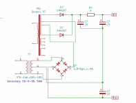
Where is the ground reference for B+?
Where is the ground reference for -Bias?
You can use that power supply as drawn for more B+, when using Self Bias. OK.
In that case the increased B+ return voltage is the -Bias (grounded; and the bottom of the self bias resistor and bypass cap is connected to that ground -Bias).
But you can not use that power supply as drawn for more B+, while at the same time using it for Fixed Bias. Not ok.
Because, if you want to use it for both B+ and -Bias, you have to ground (the + of the -Bias supply, and the - of the B+ supply).
But that means there is no increased B+ voltage in that case.
Suppose the B+ supply is 300V, and suppose the -Bias supply is -50V.
You get 350V total B+, and no bias supply.
Or, you get 300V B+, and -50V -Bias.
There is no free lunch today.
Check that out, please.
Thanks!
I guess I had my wires crossed.
However . . .
Where is the ground reference for B+?
Where is the ground reference for -Bias?
You can use that power supply as drawn for more B+, when using Self Bias. OK.
In that case the increased B+ return voltage is the -Bias (grounded; and the bottom of the self bias resistor and bypass cap is connected to that ground -Bias).
But you can not use that power supply as drawn for more B+, while at the same time using it for Fixed Bias. Not ok.
Because, if you want to use it for both B+ and -Bias, you have to ground (the + of the -Bias supply, and the - of the B+ supply).
But that means there is no increased B+ voltage in that case.
Suppose the B+ supply is 300V, and suppose the -Bias supply is -50V.
You get 350V total B+, and no bias supply.
Or, you get 300V B+, and -50V -Bias.
There is no free lunch today.
Check that out, please.
Thanks!
Last edited:
The ground is the wire connected to tap 4 of the booster transformer. I was lazy and did not add the label, sorry.OK, your cap direction is right.
I guess I had my wires crossed.
However . . .
Where is the ground reference for B+?
Where is the ground reference for -Bias?
You can use that power supply as drawn for more B+, when using Self Bias. OK.
In that case the increased B+ return voltage is the -Bias (grounded; and the bottom of the self bias resistor and bypass cap is connected to that ground -Bias).
But you can not use that power supply as drawn for more B+, while at the same time using it for Fixed Bias. Not ok.
Because, if you want to use it for both B+ and -Bias, you have to ground (the + of the -Bias supply, and the - of the B+ supply).
But that means there is no increased B+ voltage in that case.
Suppose the B+ supply is 300V, and suppose the -Bias supply is -50V.
You get 350V total B+, and no bias supply.
Or, you get 300V B+, and -50V -Bias.
There is no free lunch today.
Check that out, please.
Thanks!
On another subject, I built my first tube amp more than 40 years ago, in high school, scavenging old American TVs in Cuba. There I learned to find a way to solve this kind of issues because buying another PT was not an option. Also, this is much more fun than just buying another PT.
Hey! What about Caribe TVs?scavenging old American TVs in Cuba.
Oh, I see, they STILL work!!!!
Not kidding
Ha, an insiderHey! What about Caribe TVs?
Oh, I see, they STILL work!!!!
Not kidding
Caribe was solid state based. We used to take the KT808 sweep output transistor, it was fine for audio amps, a bit like a 2N3055, but less powerful.
The biggest advantage of the Caribes was that people started throwing away old tube TVs. Suddenly we had plenty of 6BQ6s and PTs. The good old times
Attachments

Last edited:
- Home
- Amplifiers
- Tubes / Valves
- Adding voltage to a PT