I have been thinking about a tube project (for when I have some money to try it). I am in the very early research stage and I was intrigued by the Lizzy 10Y-6L6GC power amp published in Valve magazine. It uses a transformer coupled driver stage and a parafeed autoformer CF output stage.
My idea was to try a MOSFET loaded Mu-Stage (Alan Kimmel) voltage amplifier stage and an active load CF output stage in an attempt to get high linearity and low Zout. The output transformer would of course be capacitively coupled to the output stage ala parafeed.
Has anyone built a white cathode follower output stage or any type of tube or hybrid CCS CF output stage? I would be interested in your results.
P.S. Is the Kimmel Mu-Stage a patented circuit?
White CF
I'm currently using a white cathode follower with the 6922 tube. Got some goofy results at first, but I think I'm getting it to where it needs to be, getting quite the impressive sound out of it, with the exception of some heater hum (Schottkys are on the way to alleviate *that*) It's an easy circuit, 6922 white CF, 100 ohms on plate and cathode, 100 ohm gridstops. I used 4uF auricaps for output, and 10,000 pF silver mica for input. Running at about 195V B+
6X4 rectifier into CRCLC
1uF, 1k, 10uF, 30H (600R) ,28uF. With the exception of the hum, it's dead quiet.
Ack  Use a voltage divider with impedance at least 50k (e.g., for 1/2 B+, use 100k up, 100k down) and bypass with a cap.
Voltage should be above or equal to the highest cathode voltage if it's allowed (i.e. within H-K ratings), otherwise somewhere inbetween as best you can get it. In your case, I'm guessing either 160V or 320V supply and the CF is biased in the sweet spot (approx. 160V bottom plate/top cathode given 320V) so there's about 160V between cathodes... +80V would be best to bias at, putting an even 80V H-K on each.
Tim
Use a voltage divider with impedance at least 50k (e.g., for 1/2 B+, use 100k up, 100k down) and bypass with a cap.Voltage should be above or equal to the highest cathode voltage if it's allowed (i.e. within H-K ratings), otherwise somewhere inbetween as best you can get it. In your case, I'm guessing either 160V or 320V supply and the CF is biased in the sweet spot (approx. 160V bottom plate/top cathode given 320V) so there's about 160V between cathodes... +80V would be best to bias at, putting an even 80V H-K on each.
Tim
Well, the B+ is 195, so there's no 320 to be found in the circuit, we're more at like 97 from top cathode-bottom cathode. 320 would roast the tubes, 6922 isn't very good about high voltage.
But that aside, let me make sure I get you straight. Use a voltage divider along the lines of 100k from B+ to heater CT, and 100k from heater CT to ground, with a cap bypass on each? Or am I completely misunderstanding you? I see where you're going with this, but want to be sure, I'm still a relatively new t00bie
But that aside, let me make sure I get you straight. Use a voltage divider along the lines of 100k from B+ to heater CT, and 100k from heater CT to ground, with a cap bypass on each? Or am I completely misunderstanding you? I see where you're going with this, but want to be sure, I'm still a relatively new t00bie
P.S. Is the Kimmel Mu-Stage a patented circuit?
In that case the patent have already expired, the circuit was known already in the 1940-ties and is described in principle, (together with SRPP) in "Vacuum tube amplifiers" by Valley and Wallman written 1943, probably in other books too.
Kimmel only "re-discovered" the circuit, he didn't invent it.
Regards Hans
badman said:Well, the B+ is 195, so there's no 320 to be found in the circuit, we're more at like 97 from top cathode-bottom cathode. 320 would roast the tubes, 6922 isn't very good about high voltage.
Ouch, what a waste (in the PSU resistor that is). I get 5W SE with that transformer (er, 269AX), 330V into a 6L6. Ratings, shmatings...
97V between y'say? Then half the difference (~48V) added to the bottom cathode voltage (<5V, so who cares) is a good starting point. In this case, since the top cathode has to swing voltage, it would be a good idea to bias the heaters closer to it than the lower one. It's also better to bias above a cathode than below as leakage is higher due to the heater acting as a filament cathode against the inside of the cathode sleeve. Obviously not so high as to put the bottom triode in a worse situation. So, I'd go around 60 or 70V. Off +200V, that's around 1:3, so 47k and 100k would probably work for the divider (voltage divides as R2/(R1+R2) so the resistors are 1
3-1) in ratio, thus 100k to 1/2(100k) = 47k common value). Now, you calculate the power dissipation in them for proper sizing. Tim
A few more questions.
- When one uses a CCS in the cathode of a CF output stage how do you choose the impedence of the output transformer? I am assuming Plate connected to B+, CCS between Cathode and ground. Transformer primary capacitively coupled to the cathode (i.e. para-feed CF with CCS as the cathode load).
- I am thinking about the Svetlana 6BM8 for a first design. Would the triode in this tube be able to drive the gate capacitance of a MOSFET used as the CCS in the Mu-Stage voltage amplifier or should I use two sides of a double triode (in parallel) for the Mu-Stage and a seperate power tube for the output?
- I understand that Pentodes and Beam Tetrodes work very well as CFs but I have also heard that pentodes don't like CCS loading. If you were making a CCS loaded CF would you wire it as triode or pentode? Why?
[/list=1]
Good questions on an interesting topic!
1: For max. power and minimal distortion I´d say the same impedance as if the transformer was connected to the plate as in a usual power stage. 5-8 kohms for a 6BM8.
I might be wrong here, but this is what I´ve come up with when researching for a similar project (two PL504 cathode followers loaded by an autoformer)
2: The 6BM8 triode section works at very low currents (1mA or so), so it might be a bit weak. If you want a lot of gain and voltage swing together with a bit of current, look at EC/PC86.
Don´t know what they are called is the U.S though.
3: Pentodes seems to make fine CF´s but the problem is to keep the G2 voltage constant WRT the cathode.
You can do that either with caps and resistors (which loads down the output a bit) or with at Mosfet follower that feeds the screen grid (requires a bit of circuitry including an additional PSU).
I´ll probably run my PL504´s as triodes.
Why? Simplicity and (probably) better sound.
Loading the plate of a pentode with a CCS and nothing more wouldn´t be such a great idea, but now the situation is different.
The gain of the output stage will be less than 1, CCS or not, and the the "real" load is not the CCS but the output transformer.
The ideal load for a CF is the same as the upside down situation, that is, the same operating point (voltage differences, remember) with the loads in the plate circuit. The misconception that a CF can drive more applies only to the inherent NFB in the circuit, it corrects errors in the signal but has the same current and voltage output maximums inherent in the tube and operating point.
A CCS can be ignored from an AC standpoint, that is, the load resistance is just the load itself. The operating point (a DC situation) obviously follows rules defined by biasing and the CCS.
I wouldn't trust a little triode to do much. Why use SSatanic parts anyway? Heathen!!!!
I don't know what design you're drawing from but typically the triode is used for amplification while the tetrode is the CCS/CF unit. If you're rearranging things, you might use the tetrode in triode mode instead? It'll handle more current, which is the order of the day to drive capacitance.
Pentode and tetrodes, when carelessly put in a CF circuit, are in triode mode. You need special circuitry to keep the screen at constant voltage to the cathode for it to run in true pentode mode.
Pentodes can run with CCS's just as well as any other tube, the person who claimed they don't must've been very careless. Such a situation will have massive gain (up around the mu of the pentode, which isn't an oft quoted figure; mu = Gm * Rp, so say .008 mhos * 500,000 ohms = 4000 mu!) so requires DC feedback to stabilize. Such is common practice in squalid state but almost forgotten by hard-core tubophiles.
A cathode follower arrangementl has inherent stability and work perfectly.
As to pentodes as CF's, I personally wouldn't bother adding the extra bits for it to work. If it were something that really needs the extra drive, then yes it would be well worth the effort. A high output voltage requirement, for example.
Tim
Thanks for the very enlightening discussion you guys.
Accroding to what I found on the net it corresponds to 6CM4.
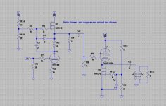
I drew a quick sketch of what I have in mind. The use of the Mu-Stage is for linearity more than for the gain advantage. The same applies for the output stage. If Zout is improved by the CCS this is fabulous but my main goal was maximum linearity without interstage feedback. The use of MOSFETs is a practical consideration. The sand is not providing any signal amplification but it should provide high performance CCSs at minimal cost, maximum reliability, and minimum bulk. I am not so much of a heathen that I would consider putting sand in the signal path of a tube amp.
Sch3mat1c; I like the idea of modulating the screen with the output (or input) signal. I suppose that either an RC network or Zener string could do this. Your recommendation?
Fuling said:Tim: Thanks for filling in my blanks
Nope, I don´t mean ECL86. I mean EC 86 or PC 86, a nice and linear little triode with high µ and reasonable gm.
Accroding to what I found on the net it corresponds to 6CM4.
I drew a quick sketch of what I have in mind. The use of the Mu-Stage is for linearity more than for the gain advantage. The same applies for the output stage. If Zout is improved by the CCS this is fabulous but my main goal was maximum linearity without interstage feedback. The use of MOSFETs is a practical consideration. The sand is not providing any signal amplification but it should provide high performance CCSs at minimal cost, maximum reliability, and minimum bulk. I am not so much of a heathen that I would consider putting sand in the signal path of a tube amp.
Sch3mat1c; I like the idea of modulating the screen with the output (or input) signal. I suppose that either an RC network or Zener string could do this. Your recommendation?
Attachments
Sch3mat1c said:Looks good, you need source resistors to set current though. Plus the signal across R3 is shunted by D1 through C1, thus no signal appears for the CCS. And R11 is superfulous because D2 has a constant voltage to ground.
Tim
Thanks for taking a look at it. The idea with the Zeners is to protect the gates of the FETs. I thought that as long as the voltage from gate to source was between 0 and the zener voltage the diode would not conduct at all. Since the MOSFET is enhancement mode the source should never be more positive than the gate (unless I really goofed up somehow). If the zener diode is chosen with a voltage significantly greater than the signal across the signal sense resistor (R3) it should not conduct in the reverse direction in normal operation either. Am I missing something there?
Is the source resistor that you mention just so that I can measure the current when adjusting the current source?
The Mu-Stage is taken directly from Kimmel. The gate voltage is set to B+/2. I think I understand the AC operation of the stage but I am a little weak on the DC biasing. My understanding is that the current through the triode is set by the self bias arrangement of R2. The current through M1 will split between the triode and the source resistor (R4). So I think that the current through M1 will be set by R4 since the excess current beyond that used by the triode will develop a voltage across R4. When that voltage aproaches B+/2 the voltage between the gate and source will be reduced to limit further increases in current. Am I close here?
Also note that I neglected to put bypass caps on the bottom resistor of the bias voltage dividers.

It appears to me that direct coupling between the stages would be possible. If so you don´t need any additional bias for the pentode.
BTW: Watch out for the limits of the cathode/heater isolation.
Are you really sure that you want to use 6BM8´s here?
Not saying that they wouldn´t work fine but I can think of some combinations of separate triodes and pentodes that might suit this application better.
Low Rp tubes allows lower turns ratio in the output transformer which leads to better frequency response. EL86 (hmm, 6CW5 I think) might be an interesting candidate for the output stage.
Regarding the voltage divider, seems that there would only be
about .18W and .08W through the resistors, so half- watt parts is plenty. The peak heater/cathode voltage is 120 positive, 60 negative, per the datasheet- I assume that's cathode WRT heater? so cathode can be much hotter than heater, but only 60V below? the problem with having the cathodes at 2 different potentials with the same heater winding for both is that one cathode (top) will be positive WRT the heater bias and one negative (bottom). So I'm thinking that perhaps operating it at 100k/30k for 45V might be a little more conservative for the heater/cathode insulation.
Again, while both are <.25W, I'll use 1/2W parts to be on the safe side. So, let me make sure we're on the same page- 100k to B+ from heater CT and 30k to ground, with the 30k bypassed by cap?
- Status
- This old topic is closed. If you want to reopen this topic, contact a moderator using the "Report Post" button.
- Home
- Amplifiers
- Tubes / Valves
- Experiences with White CF/CCS CF output stage