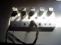
I got this at K'town last spring,, and figured its time to try and get it working!! I made an umbilical for it to try to power up with Hammond amp, or accordion amp, I've been playing with... I figured out the B+, and heater voltages,, but not sure how to connect it to an amp,, or what else it needs to operate... I have a reverb tank if it needs one...
I can't find any info on this online except for pictures,,, seems there are some Baldwin organ manuals available, but not many, and I don't know which organs this was used in... Anyone have a manual and can post the schem for this tone converter? Any chance the Sams or Ryder books have schems?
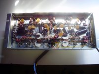
I powered up the tone chassis, and tried feeding a signal to each channel,, no joy... but there are two sets of wires coming from the same places on each channel, so I think there is an open connection that was controlled by a switch/pedal on the organ... I can try to trace the signal, and draw out the ckts,, but without the schem I may not be able build a switch/control... I built a few "controls" to activate the reverb etc on the Hammond amp, but schems are available for that one...
Gotta find someone with a manual I guess...
I'll bring the chassis to Kutztown this weekend, maybe find some ideas there!
Thanks...
I can't find any info on this online except for pictures,,, seems there are some Baldwin organ manuals available, but not many, and I don't know which organs this was used in... Anyone have a manual and can post the schem for this tone converter? Any chance the Sams or Ryder books have schems?
I powered up the tone chassis, and tried feeding a signal to each channel,, no joy... but there are two sets of wires coming from the same places on each channel, so I think there is an open connection that was controlled by a switch/pedal on the organ... I can try to trace the signal, and draw out the ckts,, but without the schem I may not be able build a switch/control... I built a few "controls" to activate the reverb etc on the Hammond amp, but schems are available for that one...
Gotta find someone with a manual I guess...
I'll bring the chassis to Kutztown this weekend, maybe find some ideas there!
Thanks...
Attachments
Last edited:
This looks to be a single channel version, with schematic:
Baldwin Panoramic Tone Converter - 1960's -12AX7 Tubes! | Reverb
Baldwin Panoramic Tone Converter - 1960's -12AX7 Tubes! | Reverb
You need the "necklace spring" hanging in the back of the organ. Top-right of first page of this PDF, or attached image. The two RCA jacks go to that. Audio goes from/to organ on the many-pin connector.
What you have is clever, sophisticated, and useless. Their delay-spring or transducers works above the audio band, 20kc. The box you have modulates audio onto 20kc carrier, sends that to the spring, returns and demodulates back to baseband.
What you have is clever, sophisticated, and useless. Their delay-spring or transducers works above the audio band, 20kc. The box you have modulates audio onto 20kc carrier, sends that to the spring, returns and demodulates back to baseband.
Attachments
Last edited:
Yep... mine is two channel... I'll try to read teh schems tho, first ones I saw online!!!!This looks to be a single channel version, with schematic:
Baldwin Panoramic Tone Converter - 1960's -12AX7 Tubes! | Reverb
Thanks
Last edited:
Thanks,,, good info,,, I saw pics of these in stand alone cabinets,, thought it may be something I can do with this one, for a tremolo preamp with a guitar amp... I tried to trace a signal thru it, and it gets modified thru teh first tx, which is attached to the stage plate of a 12AX7, but stops there...You need the "necklace spring" hanging in the back of the organ. Top-right of first page of this PDF, or attached image. The two RCA jacks go to that. Audio goes from/to organ on the many-pin connector.
What you have is clever, sophisticated, and useless. Their delay-spring or transducers works above the audio band, 20kc. The box you have modulates audio onto 20kc carrier, sends that to the spring, returns and demodulates back to baseband.
Interesting use of the HF Carrier freq. I guess that keeps room acoustics from feeding back into the reverb line.
So probably one coil is for the Osc. stage, and then one coil each for the modulate and demodulate functions.
If the demodulate functions were freq. specific, it would allow them to use the same spring for two audio channels by using two different carrier freqs. But apparently the dual channel version is using the same Osc. for both channels, so two springs needed.
Would be a good application for a 6JH8 beam deflection tube as a synchronous demod. (Put the Osc. on the deflection plates and the signal thru grid 1. Then only carrier synchronous signal adds up on the beam selected plate.)
Last edited: