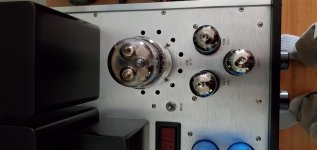
I've been the owner of this amp for over 10 years
The ALPS pot was getting very noisy and would cut out when adjusting the volume and the output tube socket connections were losing their tension.
I recently (yesterday) pulled it apart and gave it a good cleaning replaced the power tube sockets and resoldered some other poor looking connections.
The Amp is sounding great again thanks to new sockets and deoxit.
I've been trying to find a schematic for this amp but all I've found is a jpg of the schematic which is too low resolution to make out any details.
I'd appreciate any help finding a schematic.
if this is the wrong forum then I'd appreciate being pointed in the right direction
Thanks
Garth
RE: KI22 fox Schematic
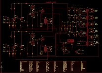
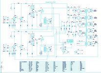
comparing the 2 schematics they are pretty much the same..
the difference I can see is in the input stage.
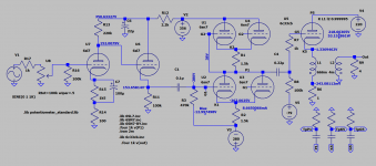
also I'm wondering is there is any difference in the components because of the preamp tube difference. The clear schematic shows the first stage is a 6SL7
my amp uses a 6SN7 and as near as I can tell that's what the schematic shows.
unfortunately I can't make out the resistor or capacitor values.
I'm new to repairing/working on tube amps (my covid project) and am curious
so please forgive any dumb questions
comparing the 2 schematics they are pretty much the same..
the difference I can see is in the input stage.
also I'm wondering is there is any difference in the components because of the preamp tube difference. The clear schematic shows the first stage is a 6SL7
my amp uses a 6SN7 and as near as I can tell that's what the schematic shows.
unfortunately I can't make out the resistor or capacitor values.
I'm new to repairing/working on tube amps (my covid project) and am curious
so please forgive any dumb questions
Attachments
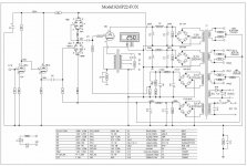
What is the primary impedance of output transformer T2?
Art
Not sure...
I'd have to take the amp apart again to test it
and it doesn't show on the schematics
Just in case if u r interested to measure the primary impedance of the output transformer:
N1/N2 = V1/V2
Z1/Z2= (N1/N2)^2
Z1=Z2*(N1/N2)^2
Where: N1/N2 turns ratio
V1/V2 : Primary voltage/Secondary voltage
Z1= Primary impedance
Z2= Secondary impedance
You need to have an audio generator set to 1KHZ connected to the secondary an ac voltmeter or scope to measure the primary voltage of the output transformer. The amp must be powered off and secondary not terminated.
Then use the above formula to calculate the primary impedance.
Art
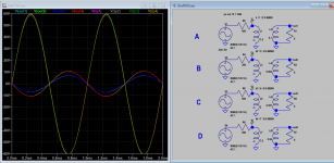
If indeed the 1st stage is 6sn7, the operating points would be quite different some thing like 60V on the plate compared with 152V when it's 6sl7.now to try and figure out the diferences
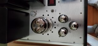
There are indeed 6 6SN7s in the amp.
6SN7EH's to be specific.
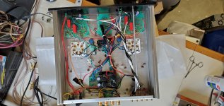
I took pictures of it when I was working on it.
once I have more energy I'll haul it back out to the shop and take some measurements.
6SN7EH's to be specific.
I took pictures of it when I was working on it.
once I have more energy I'll haul it back out to the shop and take some measurements.
Attachments
Late to the party, but I'm considering whether it's feasible to replace a failed output transformer (or more likely both, for matching) in a KI22-FOXDT, and I thought I'd post some observations. I should say that I'm not an expert on tubed amps, and way not an expert on output transformers, though that may become obvious.
On the believed-to-be-good transformer, I checked turns ratios in the manner @audiohead suggested. I had the output tube removed and the output unterminated. I came up with 4:1 for the 16 ohm tap. The other taps were consistent with that. So far, so good, I think.
That corresponds to a primary impedance of 264 ohms. I don't know if that's remarkable by itself. But if the output tubes are supposed to have an idle bias of 250mA, as I gather from the above schematic, then signal current can't be more than 500mA peak-to-peak, right? Which would make this around an 8WPC amp instead of the 22WPC spec. Am I getting the math wrong, or is this just a fairly extreme case of spec inflation?
I tried to measure the primary inductance, too, by paralleling a 2uF cap and looking for where the impedance peaked. I came up with 80Hz, which (again assuming my math is right) would correspond to about 2H for the primary. This is much lower than the inductances that are briefly discussed in @Koonw's 6c33c cathode output amp rewoked thread. Is 2H plausible?
2H is very low for primary inductance, it should be more like 100H +. Your quiescent bias current normally gives little indication of output power, but then this amp is different to your normal PP or SE amp, other more experienced builders should be able to give a better answer than myself. All I can say is that in a valve amp the OPT acts as a current transformer converting high voltage low current to low voltage high current, the more voltage swing you have on the primary the higher the OP will be.
Hope that helps, not the perfect answer but as no one else has chipped in hopefully better than nowt, Andy.
Hope that helps, not the perfect answer but as no one else has chipped in hopefully better than nowt, Andy.
- Home
- Amplifiers
- Tubes / Valves
- Antique Sound Labs KI22 Fox