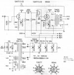
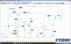
One approach to gain more output power for single ended triode amplifiers is to drive the output tube to positive grid for class A2 operation. I found two different circuits on the Internet. One uses 12AT7 and the other uses IRF610.
Can someone with more experience comments on these two approaches?
The 12AT7 seems to be biased quite low. I am not sure it can deliver 4 mA for the 6S4A tube to operate at full A2. Can I increase the bias or change the tube to something like 12AU7 or 5687?
The IRF610 for 4P1S (4P1L), on the other hand, was biased at 42 mA. It looks like good enough to drive the 4P1L. However, what are the design criteria for this MOSFET? Is IRF610 linear enough? Are there better new MOSFET for this application?
Attachments
"to drive the output tube to positive grid for class A2 operation"
The output tube /and its A2 behaviour/ define the maximum grid swing and at maximum positive grid voltage the requiring grid current.
The driver module must satisfy these requirements and must capable at least +20% headroom for both parameters.
If its clarified, you can start driver module searching (tube CF, FET SF or another), and developing its circuit with the predecessor VAS stage circuit.
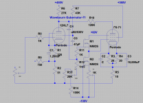
I permanently use high gm /trioded/ pentode as VAS stage (D3a, E280F, C3g etc.) and FET source follower for medium-larger output tubes (300B, 211, 801a).
The output tube /and its A2 behaviour/ define the maximum grid swing and at maximum positive grid voltage the requiring grid current.
The driver module must satisfy these requirements and must capable at least +20% headroom for both parameters.
If its clarified, you can start driver module searching (tube CF, FET SF or another), and developing its circuit with the predecessor VAS stage circuit.
I permanently use high gm /trioded/ pentode as VAS stage (D3a, E280F, C3g etc.) and FET source follower for medium-larger output tubes (300B, 211, 801a).
Last edited:
I've used MOSFETS on many occasions to provide grid drive. The nice thing about using them as followers is that they allegedly don't impart solid-state distortion products. Look at Pete Millett's A2 buffer for a nice example of proper execution. Some things are really just better serviced by solid-state, and follower/buffers are one such thing.
The circuit as shown is capable of entering A2 on short music peaks. Attempting to run a continuous sine wave for testing purposes will cause a bias shift eventually settling out somewhere into a milder level of A2 with a corresponding period of cold bias when the high drive level is removed. This cab be remedied by a zener or string of LED's across (or instead of) the cathode resistor, but this is actually a simple method of fixed bias.
The 12AT7 may be biased a bit cold, but in this application it operates asymmetrically, so the cold bias is OK. On the positive half cycle of a test signal the 12AT7 needs to SOURCE grid current into the output tube. On the negative going half cycle the circuit needs to discharge the Miller capacitance of the output tube and all associated parasitic capacitances. This duty is performed by the 22K resistor.
Assuming a fixed cathode voltage on the output tube, the follower must be able of sourcing all the grid current that the output tube can eat. I have not spent much time with a 6S4, but I'm sure that it can eat more than 4 mA. Just because the tube is biased cold doesn't stop it from sourcing current into the grid of the output tube. It's plate is tied to a B+ supply and its cathode will attempt to follow it's grid to the best of it's ability, subject to it's (the 12AT7's) capabilities.
The ability of a device to function well in a follower circuit depends on it's Gm and its "plate" resistance when driven into hard conduction. The 12AT7 is NOT an ideal candidate here. For the past 15 years I have been using a mosfet follower for A2 and AB2 designs LOTS of Gm and an ohm or two of "plate" resistance. If you really want a tube the 5687 is a far better choice than the 12AT7, so is a high Gm pentode, but it will require a screen supply.
Tubelab_com, Wavebourn,
would you see an UNSET running in A2 with Anatoly's driver fed by a voltage divider as in George's local a-g1 feedback, plus cathode drive the tube? For those tubes that are designed to run in A(B)2?
I guess George has already done similar tests during the last 10 years.
About the mosfet/tube dc-coupled buffer for output tubes, my very small experience says mosfets are better than 12AT7: they require less supply voltage (30V on top and bottom of maximum swing), are more efficient, are linear, need less space...
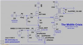
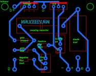
C2 listed as C - I assume 10mF too.
I drew it for myself only, to remember details. Did not change "default" values from LTSpice when not necessary. Yes, 10,000 as well.
- Home
- Amplifiers
- Tubes / Valves
- Single Ended Triode Class A2 Driver Design