I recently bought a r-core 30w dual 12v transformer for a pre amplifier board that has dual 12v or 18v in. On input side there are four wires. Black and which I will be using for the 115v and red and yellow green for the 230v. Question is what wire do I use for the ground or do I just isolate the red and yellow green from shorting anything out and ground to the chassis from the iec input? On the secondary’s there are two blue and two brown wires. On the pre amplifier board it is dual 12v-0-12 or 18v-0-18. Question is what wire do I use for 0? I’ve seen it done one wire each for + and - and the other two wires for 0 i believe but I want to be very sure I wire everything correctly so that’s why I’m asking. Any help would be greatly appreciated
Attachments
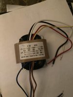
Screen (a shield, to be grounded to the chassis) is the yellow/green wire.
Exactly what is your line voltage, 115VAC or 230VAC?
For 115VAC, use the black and white wires, and insulate (do not use) the red wire.
For 230VAC, use the black and red wires, and insulate (do not use) the white wire.
Connect the IEC socket ground terminal directly to the chassis.
Exactly what is your line voltage, 115VAC or 230VAC?
For 115VAC, use the black and white wires, and insulate (do not use) the red wire.
For 230VAC, use the black and red wires, and insulate (do not use) the white wire.
Connect the IEC socket ground terminal directly to the chassis.
Last edited:

It's not 12-0-12 it's a 12-0 and 12-0 secondaries transformer
For the primary side it's what @rayma stated not as you write
You probably asking for the secondary side in order to have 12-0-12 ouput you have connect one pair of blue and brown wires together. Because the polarity of the secondaries probably is not stated you have to try pairs. Most probably is the ones in the middle (Blue Brown). Just tie them together and measure with a multimeter with one probe in the the tied pair and the other probe to one of the other wires, you should see more than 12 VAC each time (you can have little less or more according to your main voltage if lower of higher than 230V) The connected wires are used as 0 as you write.
I assume you have a multimeter
Edit: although it's kind of difficult to cause trouble to transformer (it will just buzz loudly) just say if something is not clear to you
Last edited:
Primary side: Black = Neutral, White = 115 VAC, Red = 230 VAC, green/ yellow is shield for chassis, or Earth.
Use Neutral as common, and the other two wires, wire them to suit your mains voltage, insulate the other.
Secondary side is two windings, one each pair in Blue and Brown.
Clearer?
Use Neutral as common, and the other two wires, wire them to suit your mains voltage, insulate the other.
Secondary side is two windings, one each pair in Blue and Brown.
Clearer?
Screen (a shield, to be grounded to the chassis) is the yellow/green wire.
Exactly what is your line voltage, 115VAC or 230VAC?
For 115VAC, use the black and white wires, and insulate (do not use) the red wire.
For 230VAC, use the black and red wires, and insulate (do not use) the white wire.
Connect the IEC socket ground terminal directly to the chassis.
I’m using 115v and I know to use the black and white. The grounding part I was asking about but you just answered it for me with the green/yellow wire. Thanks
Thank you, you just answered my question. So twist one blue and brown together and that is my 0 correct? And yes I have a multimeter. Thank you for the helpIt's not 12-0-12 it's a 12-0 and 12-0 secondaries transformer
For the primary side it's what @rayma stated not as you write
You probably asking for the secondary side in order to have 12-0-12 ouput you have connect one pair of blue and brown wires together. Because the polarity of the secondaries probably is not stated you have to try pairs. Most probably is the ones in the middle (Blue Brown). Just tie them together and measure with a multimeter with one probe in the the tied pair and the other probe to one of the other wires, you should see more than 12 VAC each time (you can have little less or more according to your main voltage if lower of higher than 230V) The connected wires are used as 0 as you write.
I assume you have a multimeter
Edit: although it's kind of difficult to cause trouble to transformer (it will just buzz loudly) just say if something is not clear to you
Just tie them together and measure with a multimeter with one probe in the the tied pair and the other probe to one of the other wires, you should see more than 12 VAC each time (you can have little less or more according to your main voltage if lower of higher than 230V) The connected wires are used as 0 as you write.
Probably not what you meant but like you wrote it, it could be understood as: TS should measure between the point where the blue wire and brown wire are connected (so with one probe on the centre tap or "0" point) and one of the two 'free' wires. But like that you will allways measure 12 Vac (or a little higher because there is no load) no matter which of the two blue wires is connected to one of the brown wires
TS should measure between the two 'free' wires. If than you measure 24 Vac (or a little higher) the wires are connected the proper way. But if you measure 0 Vac (or close to that) than the wires are connected wrong (than use the other blue wire to connect to the same brown wire you used for tying to a blue wire).
Last edited:
The two secondaries have to be in phase and it matters which blue to connect to which brown for 0V.
to test this you have to power the primary
connect the left brown to the AC meter, the other brown to the left blue and the right blue to the meter. if it shows 24Veff it is ok like this, if it shows 0V change the blue wires and see if 24V are shown.
to test this you have to power the primary
connect the left brown to the AC meter, the other brown to the left blue and the right blue to the meter. if it shows 24Veff it is ok like this, if it shows 0V change the blue wires and see if 24V are shown.
Great, for the record PFL200 is right (and bansuri) because you don't have oscilloscope in order to see the phase, it's best to measure 24v across the two free wires.
You see, for the manufacturers it's big hassle to put two black dots in the diagram when for some reason they are not willing to use the standard 4 color insulation for secondary wires. In those chinese r-cores I've seen all kind of colored wires, purple, pink... and all don't indicate phase, like there is a rule not to do it or they come from same factory.
Kind makes me avoid them and it's a pity because there is no other source for r-cores in Europe.
OK, enough wining.
- Home
- Amplifiers
- Tubes / Valves
- R-core transformer help