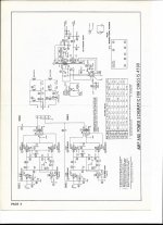
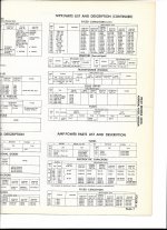
Hi all, reading old post and still confused. The schematic and parts list are attached. When I re-capped this in 2011, I put NP orange dips in place of C71, C72, C73 & C74 which show as polarized. (Amp has not been running except a couple of times to test.) I am having difficulty locating anything close to 0.1 mF polarized, 400V . The search bars on most suppliers sites are pretty useless, but it looks like the only polarized caps are electrolytic and they just don't come that small. There are some Aerovox .1 uf @ 400 v capacitors on Ebay. They are 50s/60s parts. would they work? I' dubious about them.
Attachments
You can use non-polarized capacitors in any position. But high values of capacitance and/or voltage are normally only available as electrolytics which normally are polarized.
So if you need to use electrolytics because they are the only ones available for a particular combination of value and voltage, you must pay attention to the polarity of the voltage across them.
If you can use non-polarized because they are available in that voltage/value, you don't need to worry about the polarity of the voltage across them.
Jan
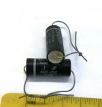
The circle marking around the cap at one end is the indicator of the outside foil (or is it the other way).
Unless you want a leaky cap, the non-electrolytic makes a great coupling cap.
(of course we do not like leaky caps there).
Old schematics sometimes used the same symbol for electrolytic and non-polarized caps.
The cap symbol with straight and curved, comes from variable caps, the circle is the rotor.
But then it was adopted for electrolytic caps, with the curved as negative, and straight for positive.
I can not read the schematics, they are too small.
I am guessing you are talking about coupling caps, 0.1 @ 400V is one of several typical values.
If you test the B+ voltage when the amp is warming up, you may find it is more than 400V.
A slow warming plate will be at the B+ voltage (no drop in the plate load resistor).
Because different tubes can warm up at different rates, and B+ can exceed 400V at warmup time, I use 600V coupling caps.
I replace old coupling caps.
Many are leaky, an Ohmmeter may, or may not see that, but if you see + voltage at the next tube's grid, either the cap is leaky, the grid resistor is larger than the tube max Rg spec, or the tube may be gassy.
Last edited:
The parts list specifies several brands/types of capacitors that can be used for C71 to C74. I googled on Cornell-Dubilier CUB4P1 with this result (see page 426): https://www.technicalaudio.com/pdf/Electronics_Catalog_Extracts/Cornell_Dubilier_capacitors_1960_REM_24.pdf
Old schematics sometimes used the same symbol for electrolytic and non-polarized caps.
I replace old coupling caps.
That is correct.
Old service technicians (like me) are familier with the dated ways of symbols on schematics.
Same goes for resistors - in "the old days" a 10K ohm resistors may be marked as 10M.
So it confuses new guys, thinking it's a 10 megohm resistor.
Ya they are fine.
Polypropylene are better, as are Polycarbonate, but "mylar" is good enough.
Experience says these Kyet CBB caps are perfectly fine and they are affordable!
KYET | KYET KP104J2J1501 | Polypropylene Film Capacitors (CBB) - LCSC.COM
I also like Carli.
Carli | Carli DB104J2JD59H200D9R | Polypropylene Film Capacitors (CBB) - LCSC.COM
Last edited:
- Home
- Amplifiers
- Tubes / Valves
- polarized capacitors