OK, long shot here. Taking FB to the VAS from the primary side of the OPT (output tube plate) is a simple matter in SE amps but is there a way to take feedback from the primary side to the VAS in a PP amp? If you take it from just one output tube it might be OK for normal signals but I am thinking that things would go completely nuts when there is an overload or even class AB operation. Reasonable assumption? Any clever tricks or just bite the bullet and buy a scope?
I think, YES.
The question is what is the benefit to do so.
The benefits are avoiding the complex reactive elements of the OPT in the loop thus reducing instability issues and avoiding trying to beat the OPT into submission with wild signals under overload conditions.
Philosophically I would prefer to drive the OPT with a clean relatively low Z signal and let the OPT run free as it were. Perhaps plate to grid around the output tubes would be adequate but I am not sure how well that would work if driven by a LTP or Paraphrase.
You are right, if one tube cuts off (Class AB), then only using the plate signal from just one output tube would have to rely on super coupling from one half of the primary to the other half of the primary.
Not ideal.
Perhaps you might consider using 3 stages.
A phase splitter with a current sink for the parallel cathodes; a pair of driver tubes, and the output tubes.
You can feedback both plate signals to the respective cathodes of their driver tubes.
You could either DC couple those signals; or use a series resistor and a coupling caps for each plate signal to the driver cathode (the coupling caps will not provide feedback at extremely low frequencies, so calculate the capacitors carefully). The gain at extremely low frequencies will be what the gain was before the negative feedback is applied.
Last edited:
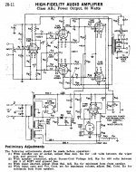
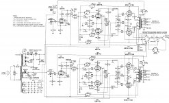
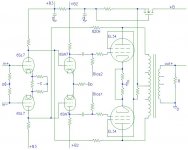
This design broke the internet some years ago. Pentode LTP input stage to pentode PP output stage with feedback from plate to plate:
Posted new P-P power amp design
Posted new P-P power amp design
Two examples. The one with the 807's runs in class A. The one with the 7027A's (from a RCA Receiving Tube Manual) runs in class AB1.
Attachments
The benefits are avoiding the complex reactive elements of the OPT in the loop thus reducing instability issues and avoiding trying to beat the OPT into submission with wild signals under overload conditions.
Philosophically I would prefer to drive the OPT with a clean relatively low Z signal and let the OPT run free as it were. Perhaps plate to grid around the output tubes would be adequate but I am not sure how well that would work if driven by a LTP or Paraphrase.
If low distortion is your goal, because of wildness of OPT, you really need negative feed back after OPT to fix the its distortion.
Some amp has a cap between one of OPT screen tap and the feedback point. It essentially is Miller compensation. It creates a tight negative feedback on OPT primary side. I believe that cap resolves stability issue and lowers the Z of output tube.
Lots of contemporary amps use voltage feedback from just before the output transformer. It reduces the impedance driving the output transformer, better for small signal magnitude response, better for large signal third order output transformer distortion performance.
The classic design dilemma comes from including or not the output transformer within the feedback loop. Lots of bandwidth devolved.
Modern fashion in valve amplifiers could be described as an evolutionary result of the very real difficulty of adapting idealized "op-amp" thinking to the messy LC world of super fast valves (relative to semi-cons) and large impedances (relative to the Earth's 100-ish Ohms).
Folks have gone from the late 1950s DTN Williamson design of long loop feedback (the basis of all modern semi-con thought) to the contemporary "it's too hard to do feedback right, so it must be evil" to a newer perspective of integrating local feedback paths.
Sometime soon the classic two stage feedback from output plate to input cathode will get a hip name and be immortalized.
All good fortune,
Chris
As the OPT is one of the worst offender in an amplifier, it is logical to include it in the (or "a") FB loop, but this is difficult for stability reasons.
A reasonable tradeoff is to implement both pre- and post-OPT feedback loop, with the pre- loop dominating at high frequencies and the post-loop dominating at low frequencies.
Kind of TMC and TPC for tubes
A reasonable tradeoff is to implement both pre- and post-OPT feedback loop, with the pre- loop dominating at high frequencies and the post-loop dominating at low frequencies.
Kind of TMC and TPC for tubes
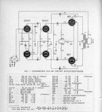
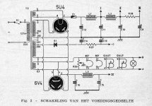
Don't forget the Citation II. Crossed Local N Fdbks to the driver grids. (pic 1) Thorsten Loesch also uses a similar scheme. (pic 2, this was a developing clone, missing the caps for 6SN7 grids here)
The Dynaco ST70 used the small cap from the primary side. Similar to Miller Comp. One could include a series resistor to set a higher freq. for it to set in.
The distortion in OTs (other than freq. roll-off) comes from the primary side magnetizing current, so local N Fdbk -WILL- fix -most- of that. (see last paragraph for -ALL- of it) Just use some modest global N Fdbk to fix the freq. roll-off from distributed winding cap. and leakage L.
Using the OT's UL taps for the local Fdbks gets you a more closely coupled, to secondary, pick-off point for more highly accurate local Fdbk. There will be some phase shift there, but not as much as at the secondary.
Wavebourne uses multiple nested Fdbk loops, ULTRA territory.
If you have a curve tracer, you can select 12HL7 (pic 3) or 6LQ8 drivers with -PRIMO- triode mode curves from the screen grids. Then you can do local N Fdbk to the screen grids alone (crossed) and not lower the input Z of the diffl. driver stage grids. (as the usual local to driver grids does cause) This scheme, incidentally, makes the output tubes emulate the linear driver triode.
(Advanced: proper proportional scaling of the Fdbk signals to the driver stage output signals can get you constant impedance at the screen grids, so no Mosfet follower needed there, a Jan Veiset scheme)
Some small value current sampling resistors in the output tube cathodes can be used to introduce a neg. resistance Fdbk back to the driver stage also. This can be tuned to remove the primary side winding resistance, where magnetizing current would cause some small V drop in series to the output (not seen at plate V pick-offs). This is ULTRA amplifier territory.
Attachments
Last edited:
As the OPT is one of the worst offender in an amplifier, it is logical to include it in the (or "a") FB loop, but this is difficult for stability reasons.
A reasonable tradeoff is to implement both pre- and post-OPT feedback loop, with the pre- loop dominating at high frequencies and the post-loop dominating at low frequencies.
Kind of TMC and TPC for tubes
I have heard this claim about OPT distortion but has anyone really quantified the distortion of a typical OPT driven by the lowish impedance of an output stage with local feedback? If they are so horrible then a lot of zero gNFB amps ought to sound really bad and trying to force them into linearity with FB might indeed lead to some wickedly difficult wave forms in the transformer itself perhaps causing its own problems.
It would be nice to see some measurements of open loop OPTs at different driving impedances. It would be interesting to compare to loudspeaker distortion (a coil and mechanical system outside the FB loop) as well. Just for context of course.
I am not saying that the OPT is not the largest source of distortion I really don't know but it seems a really interesting matter for study.
Also I wonder about the tactic of using local FB before the OPT and then putting the secondary in the cathode circuit of the output tubes. The question of course is whether the cathode FB is sufficient to make any real difference.
P-P OTs have very low magnetizing current except at the low freq end. And they have high primary inductance. (so lowish magnetizing current dist.)
SE OT's with an air gap are where magnetizing problems abound. (lower inductance means higher magnetizing current)
Cross-over distortion from the tubes in P-P are where the main distortion arises there. Usually fixed by biasing up to moderately high idle currents. Local N Fdbk fixes this too.
Then there is Ri (or Rp) variation with current as the next problem, along with gm variation. Moderately high idle current or local N Fdbk fixes this too.
Crazy drive fixes this as well. UnSet too.
Last edited:
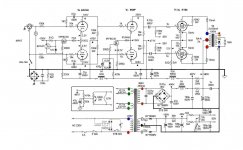
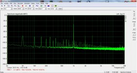
I feel very good with my amp -schematic attached- using this principal https://pearl-hifi.com/06_Lit_Archive/02_PEARL_Arch/Vol_01/Sec_01/065_Dsgn_Fctrs_for_PwrAmps.pdf as discussed here https://www.diyaudio.com/forums/tub...h3-3rd-harmonic-cancellation.html#post4571822 I attach FFT at 1W and at 16W -max power. Not breath taking figures but it does it with zero GNFB.
Attachments

An interesting article related to the topic.
http://www.dalitech.com/Resources/Measuring Output Transformer Performance.pdf
http://www.dalitech.com/Resources/Measuring Output Transformer Performance.pdf
PFL200,
Thanks for your schematic in Post # 7.
So many of those suggestions in this thread will work very well, lots of choices.
But . . .
The reason I suggested that kind of feedback in my earlier post, is that it:
Uses both output plate signals ('perfect' primary 1/2 to 1/2 coupling not required)
It does not drive both grids of the driver tubes, and does not drive both grids of the phase splitter.
The feedback loop is medium long, not long.
Example:
Instead, another circuit proposes that a phase splitter has to drive the driver tubes of a 3 stage amp. Output tube feedback to the grids of those driver tubes, that causes a low impedance load on the phase splitter, making the phase splitter's job harder.
Or, dual plate to plate feedback is used, making the load impedance on the plates that drive the output tubes see a low impedance.
Instead, output tube plates fed-back to earlier tubes cathodes is easy to control, and with less effect on the load on those tubes that drive the next set of grids.
It is all just a choice as to what you prefer.
Any of those methods can be extremely good, if the design and implementation is carried out very well.
I have heard this claim about OPT distortion but has anyone really quantified the distortion of a typical OPT driven by the lowish impedance of an output stage with local feedback?
I have, in a 6384 SE amp with fairly heavy local feedback (so nice and low driving impedance on the transformer primary, less than 100 ohms for sure).
Distortion on OT primary:
100mW - 0.038%
500mW - 0.086%
1W - 0.12%
2W - 0.17%
5W - 0.28%
10W - 0.44%
Distortion on OT secondary:
100mW - 0.045%
500mW - 0.10%
1W - 0.14%
2W - 0.21%
5W - 0.35%
10W - 0.51%
This was with an Edcor 5k:8 25W transformer. I'd say the amplifier is definitely the main distortion component, but the transformer's distortion contribution is not insignificant, especially if you look at harmonic contribution. The OT adds significant higher-order harmonics at higher levels.
Thank you for that data SS. At what frequency were those measurements made? Being a SE transformer this presents some essentially worst case data as an un-gapped PP would likely have lower numbers.
BTW guys. While looking at some other stuff I found references to UL amps with feedback taken from the UL taps instead of the plate. What would be the advantage of such an arrangement?
BTW guys. While looking at some other stuff I found references to UL amps with feedback taken from the UL taps instead of the plate. What would be the advantage of such an arrangement?
The UL taps are generally better coupled to the secondary than the plate taps. Best winding interleave generally around them. This is so the UL Fdbk will work well in conventional UL mode. There will be more phase shift than the plate taps (relative to the tube output), but less than from the secondary. The UL tap is like an autoformer. Less than full load loading it down to cause a phase shift, and primary current thru it is direct from the plate. It's going to be a scaled version of the plate voltage except for just a tiny amount better coupling to the secondary (per turn) than the plate tap. ( reduced leakage L per turn to the secondary)
Last edited:
- Home
- Amplifiers
- Tubes / Valves
- Possible to do feedback from before OPT on PP amps?