I have begun a new amp incorporating parafeed, transformer drive and Ultrapath. I already have all of the necessary iron and would welcome comments.
I'm not sure what size small cap I will need to lift the rectifier output from the choke input filter value of 450v to the 520v I need, and I'm not sure if I want to use 10uF or 20uF caps in the driver supply. The cathode resistors are only best guesses as well. Most of the PS caps will be CDE oil motorstarters, as well as the parafeed cap. I want to be able to switch rectification and possibly 300 cathode resistances in order to vary operating points.
I will breadboard (actually plywoodboard!) and fine tune the complete PS through the loading coils and driver transformers using power resistors to draw the necessary current. When I'm sure I have the proper currents and voltages available for the plates I'll repeat the process with tubes to get the cathode resistor values.
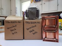
Doc B might get a kick out of the transformer/choke picture and the Valve magazine page with the Electronic Tonalities add for the trannies. I was a member of Valve in the late 90's and bought them from him then. $600 a pair for full nickel at the time - those are not the Pinstripes or the Juniors... The chokes are 50H/100ma units I got from Japan a decade ago. I can't remember who made them.
I'm not sure what size small cap I will need to lift the rectifier output from the choke input filter value of 450v to the 520v I need, and I'm not sure if I want to use 10uF or 20uF caps in the driver supply. The cathode resistors are only best guesses as well. Most of the PS caps will be CDE oil motorstarters, as well as the parafeed cap. I want to be able to switch rectification and possibly 300 cathode resistances in order to vary operating points.
I will breadboard (actually plywoodboard!) and fine tune the complete PS through the loading coils and driver transformers using power resistors to draw the necessary current. When I'm sure I have the proper currents and voltages available for the plates I'll repeat the process with tubes to get the cathode resistor values.
Doc B might get a kick out of the transformer/choke picture and the Valve magazine page with the Electronic Tonalities add for the trannies. I was a member of Valve in the late 90's and bought them from him then. $600 a pair for full nickel at the time - those are not the Pinstripes or the Juniors... The chokes are 50H/100ma units I got from Japan a decade ago. I can't remember who made them.
Attachments
PSUD2 is a great idea.
I am not a software guy, I hate software.
An example [manual, not software] power supply calculation:
(in round numbers)
350VAC-0-350VAC secondary
Center tap, and Solid state Full Wave (2 diodes) less than 1V forward drop, one diode at a time.
Choke input filter: 350 x 0.9 = 315VDC (and a 100 Ohm choke, and 100mA (total, 2 channel stereo) will add a drop of 0.1A x 100 Ohms = 10V
315V - 10V = 305V
(you Must have at least enough Henrys to meet the Critical Inductance requirement for the Choke, in order to make it a valid choke input supply).
305VDC at the choke Output (with a capacitor to ground there).
60Hz mains, f = 120Hz rectified full wave.
Suppose you use a 10uF cap from the rectifiers, before the choke.
That is a capacitor input filter.
Xc = 1/(2 x pi x f x C)
Xc = 130 Ohms
Approximate peak to peak voltage at the 10uF cap
130 Ohms x 0.1A = 13V peak to peak
13/2 = 6.5V
350VRMS = 495V peak
495V peak - 6.5V = 488.5V at the 10uF/Choke junction.
488.5V -10V drop in the choke - 468.5VDC at the choke output.
Just adjust the primary voltage, the capacitor, etc. to get the voltage you want.
I did not include the additional voltage drops due to the load on the power transformer,
The primary DCR (times the primary to secondary step-up ratio), and the secondary DCR will cause additional drops (larger voltage drop with a cap input filter, than with a choke input filter; because the transient current to a cap input filter is much larger than the current to a true choke input filter.
Whatever you do, do Not forget to add a bleeder resistor(s) to discharge the B+ capacitors.
Safety First!
Prevent the "Surviving Spouse Syndrome".
Last edited:
I have begun a new amp incorporating parafeed, transformer drive and Ultrapath. I already have all of the necessary iron and would welcome comments.
I'm not sure what size small cap I will need to lift the rectifier output from the choke input filter value of 450v to the 520v I need, and I'm not sure if I want to use 10uF or 20uF caps in the driver supply. The cathode resistors are only best guesses as well. Most of the PS caps will be CDE oil motorstarters, as well as the parafeed cap. I want to be able to switch rectification and possibly 300 cathode resistances in order to vary operating points.
I will breadboard (actually plywoodboard!) and fine tune the complete PS through the loading coils and driver transformers using power resistors to draw the necessary current. When I'm sure I have the proper currents and voltages available for the plates I'll repeat the process with tubes to get the cathode resistor values.
Doc B might get a kick out of the transformer/choke picture and the Valve magazine page with the Electronic Tonalities add for the trannies. I was a member of Valve in the late 90's and bought them from him then. $600 a pair for full nickel at the time - those are not the Pinstripes or the Juniors... The chokes are 50H/100ma units I got from Japan a decade ago. I can't remember who made them.
Nice work! In the last couple of weeks I dragged out my TFA-2004NiJrs, BAC-80's, and 3 pairs of NOS VV52's. Might finally get to build the Blues Master...
Cheers,
Mike