Class A amplifiers, as you're considering, draw essentially constant DC current from the B+ supply. The valve spends just as much time at less than idle current as it does at more than idle current. So, not an issue. The 150mA spec number is conventionally for DC current with a not-extreme capacitor input. Again, not an issue for you.
Cathode feedback, as Fuling mentioned, is easy to do, free and has little effect. Instead of connecting the paralleled cathode bias resistor and bypass capacitor to signal ground, they're lifted and attached to the secondary output. With an estimated 3 Watt output at 8 Ohms, that's 4.9 Volts feedback where forward signal level is 21.2 Volts. A fraction of a dB, but easy and free. Must get the transformer's polarity right.
All good fortune,
Chris
Just a quick reply as I´m just about to test/blow up my latest amp prototype:
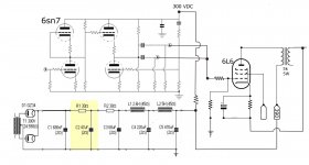
The attached image shows how to get some local feedback around an output tube by connecting the OPTs secondary winding between cathode and ground.
As I mentioned before, this doesn´t work well with all transformers but when it works it effectively lowers the Rp and Mu of the tube. Worth a try since it takes very little effort and requires zero extra components.
Attachments
Seems like Chris Hornbeck posted pretty much the same this as I was writing, while I was writing it
It is true that CFB from the speaker winding usually gives little effect but at least it comes for free. There is an old thread where George from Tubelab experiments with 6AV5 and Edcor transformers and got some very good results by adding CFB.
It is true that CFB from the speaker winding usually gives little effect but at least it comes for free. There is an old thread where George from Tubelab experiments with 6AV5 and Edcor transformers and got some very good results by adding CFB.
If the 4.9Vrms output voltage, and the 21.2Vrms grid drive are true, then the negative feedback is:
20 x Log(4.9V/21.2V) = -12.7dB
That is quite a lot of negative feedback
And, that has reduced the amplifier gain to about 1/2 of what it was, before the ~ 12dB negative feedback was applied.
20 x Log(4.9V/21.2V) = -12.7dB
That is quite a lot of negative feedback
And, that has reduced the amplifier gain to about 1/2 of what it was, before the ~ 12dB negative feedback was applied.
Last edited:
-12.7dB
Is this really correct?
Adding 4,9Vrms feedback signal to 21,2Vrms grid drive should result in a new input sensitivity of ~26Vrms, wouldn´t that be more like 1,5dB of feedback?
Maybe I gave my example poorly. Sensitivity of the output stage, for full output, is reduced from 21.2 Vrms to (21.2 + 4.9) Vrms, so not much difference.
This connection was a staple of Audio Research amplifiers back in the days of banks of GE 6550As. The higher the output stage Gm, the more the feedback effect. Also worth doing for little hot-pants bottles like EL84s and such.
All good fortune,
Chris
This connection was a staple of Audio Research amplifiers back in the days of banks of GE 6550As. The higher the output stage Gm, the more the feedback effect. Also worth doing for little hot-pants bottles like EL84s and such.
All good fortune,
Chris
2.28dB of negative feedback.
This seems like a much more reasonable number, yes.
Here is what George wrote about his CFB experiments with Edcor transformers and 6AV5:
https://www.diyaudio.com/forums/tubes-valves/74650-edcor-meets-6av5-3.html#post867969
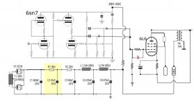
I took the liberty of making some changes to your schematic, just for clarification.
I would suggest 560R 5W and 100uF 50V on the cathode, a 330k grid lead, 1k carbon composite gridstopper on G1 and 220R >1W carbon composite on G2.
These values are by no means optimized but they should work.
I would suggest 560R 5W and 100uF 50V on the cathode, a 330k grid lead, 1k carbon composite gridstopper on G1 and 220R >1W carbon composite on G2.
These values are by no means optimized but they should work.
Attachments
Why is there a voltage divider at the intersection of first and second stages of the preamp? Also, why the double output capacitors?
Calculation of gain reduction by feedback should be a factor of (21.2 + 4.9) / 21.2 = 1.23 or about a smidgen in dBs.
All good fortune,
Chris
Calculation of gain reduction by feedback should be a factor of (21.2 + 4.9) / 21.2 = 1.23 or about a smidgen in dBs.
All good fortune,
Chris
Thank you Fuling, I think I had the grid leak and grid stopper resistors backwards. Chris, is that the voltage divider you are referring to? I will clean this up in next version. As far as the two output caps, a feature of the Aikido pcb is that it affords room for two or three different output caps. I neglected to draw in the switch that selects 1,2, or both. Currently I have a paper and poly cap. I cant tell the difference between them, so I like to think they both sound good.
Now I re read your question, you are aking about the voltage divider within the preamp. I will not do justice to that question, but I will happily refer you to the tubecad notes that explain. As far as I ca discern, it has something to do with the way the Akido circuit cancels out PS noise by playing two halves of each triode against the other. I will look for the link that explains
I believe the answer to your question about the preamp circuit lies here:
New Tube Circuit: The Aikido Amplifier
This is th page that I remember reading before building the premp. Beware, it mentions genius, so read at your own risk.
New Tube Circuit: The Aikido Amplifier
This is th page that I remember reading before building the premp. Beware, it mentions genius, so read at your own risk.
So they're to protect against catastrophic stupidity. Happens, I guess.
John Dee was an alchemist (but so was Newton) who saw the way forward into science, at a time when people still believed in witches. We're now living in a time when science, or even clear thought, is devalued. Foolish, foolish humans.
All good fortune,
Chris
John Dee was an alchemist (but so was Newton) who saw the way forward into science, at a time when people still believed in witches. We're now living in a time when science, or even clear thought, is devalued. Foolish, foolish humans.
All good fortune,
Chris
- Home
- Amplifiers
- Tubes / Valves
- More help with low watt output stage please