Yes, I know, but since the circuit is very simple SE amplifier with resistor loaded input stage (which has poor PSRR also), I must make the power supply as good as I can. In the end amplifier is just modulated power supply ")
I heard the difference and I trust my ears. Its a pity that I dont have any oscilloscope or spectral analyzer anywise I would have proved it already. I also 50% know what is the cause of the harshness (thanks to you guys!), and I 20% know how to get rid of this. This is what I need to do.
Or I can improve my driver stage by using CCS in the anode instead of the resistor? This will improve PSRR, or not?
Best regards, Michal

The ripple is 10mV. Using smaller input cap I can reduce the charging current peaks even further but with bigger ripple and smaller voltage. Everything around 270 starts to look pretty good.
By the way. Will it make a difference if I place the 50 ohm resistor between power transformer seconday and the bridge, r like it is in the schematic?
Best regards, Michal
Last edited:
Yes, I know, but since the circuit is very simple SE amplifier with resistor loaded input stage (which has poor PSRR also), I must make the power supply as good as I can. In the end amplifier is just modulated power supply
I heard the difference and I trust my ears. Its a pity that I dont have any oscilloscope or spectral analyzer anywise I would have proved it already. I also 50% know what is the cause of the harshness (thanks to you guys!), and I 20% know how to get rid of this. This is what I need to do.
Or I can improve my driver stage by using CCS in the anode instead of the resistor? This will improve PSRR, or not?
Best regards, Michal
i would use voltage regulators instead, the mosfet follower types with some zener diodes..
Michal, there is no difference in PSUD display when the 50R is after the bridge rectifier to when it is included in the transformer winding resistance.
Those simulated charging current peaks have no practical impact on part operation (eg. for ss diode choice or stress).
The 10mV ripple is for main B+. The ripple at the input stage will be different (presumably a lot lower) and you can't really assess PSRR at the input stage from that simple sim, so your presumption that "I must make the power supply as good as I can" may be ill-informed or directed. What you 'heard' may well be from other issues with your amp.
the difference between solid state and vacuum tube rectifier is like night and day.
Don't believe any of that.
The old Bogen MO200 uses ordinary Si rectifiers (yes from 1963-68), once the design is well sorted, Gillespie showed they sound excellent.
I have a pair and they are just gorgeous.
All those old MO/MX amps use the same design of PSU with voltage doubler also AND a steel chassis (!), apparently all wrong according to modern folk tales.
(You can improve on the screen grid supplies with a choke in the 310V to reduce ripple).
In my own amp design I use ordinary bridge rectifiers with both a Choke input filter for the main HT, and a miniature TV damper diode to give it gentle warm up.
The screen supply is regulated via a proper triode and cold cathode VR device (300V) from a 2nd Toroid power transformer winding, so peak currents on the main HT rail doesn't show up in the main AF amp/driver supply.
Everyone has remarked on how truly wonderful, and how astonishingly powerful the (PPP Pentode) amp is for its size (2 x 50W per channel) with very low IMD and THD.
Ultra clean, no compression, high power and low noise all in one hit with an amp weighing just 13kg.
Fastron "RF choke" versus Bourns mH fixed inductor - is one preferred?
@Eli - For this purpose, is there any important difference between a "RF choke" and the Bourns fixed inductors you linked to, other than current handling? The datasheets are a little sparse. Searching Mouser for "RF choke", I find a lot of lower current handling chokes by Fastron. For a B+ of max 200 mA, would you prefer one type over the other?
many thanks, Derek
A big 1st filter cap. can work well, IF ... A LC section made from a high current RF choke and a 1000 pF. mica or C0G ceramic cap., between the 1st filter cap. and the "typical" filter choke, removes the HF noise routine CLC filtration doesn't cope with well.
... would a low value speaker crossover choke in the sub mH range work (in the negative rail of course). ...
... This sort of part definitely works. Make certain to pick something with adequate current handling capability.
@Eli - For this purpose, is there any important difference between a "RF choke" and the Bourns fixed inductors you linked to, other than current handling? The datasheets are a little sparse. Searching Mouser for "RF choke", I find a lot of lower current handling chokes by Fastron. For a B+ of max 200 mA, would you prefer one type over the other?
many thanks, Derek
Your amp is pushpull pentode. Pushpull amps are MUCH more tolerable to any noise and hum in power supply because of their balanced topology. Single ended tube amp will not do that. The simpler your amp and whole audio chain is, the bigger differenge between the components will be.Don't believe any of that.
The old Bogen MO200 uses ordinary Si rectifiers (yes from 1963-68), once the design is well sorted, Gillespie showed they sound excellent.
I have a pair and they are just gorgeous.
All those old MO/MX amps use the same design of PSU with voltage doubler also AND a steel chassis (!), apparently all wrong according to modern folk tales.
(You can improve on the screen grid supplies with a choke in the 310V to reduce ripple).
In my own amp design I use ordinary bridge rectifiers with both a Choke input filter for the main HT, and a miniature TV damper diode to give it gentle warm up.
The screen supply is regulated via a proper triode and cold cathode VR device (300V) from a 2nd Toroid power transformer winding, so peak currents on the main HT rail doesn't show up in the main AF amp/driver supply.
Everyone has remarked on how truly wonderful, and how astonishingly powerful the (PPP Pentode) amp is for its size (2 x 50W per channel) with very low IMD and THD.
Ultra clean, no compression, high power and low noise all in one hit with an amp weighing just 13kg.
What about to take big ferrite beads and slide them over wire that goes to the main 5-10H choke?
Your amp is pushpull pentode.
Pushpull amps are MUCH more tolerable to any noise and hum in power supply because of their balanced topology.
A fully balanced pushpull amp (No phase invertor) is TWO single ended amps back to back. Pentodes have the lowest IMD, and full balanced amps (balanced XLR input) can be very simple designs, even DC coupled.
The Bogen amps weren't pentodes they were specialised semi-frame grid beam tetrodes.
Beam tetrodes have much higher IMD characteristics than pentodes, especially the xL6, xCA7, KTxx crowd.
Use fast diodes and put an RC snubbing network across the transformer secondary. Easy.
Yes.
After that, there're still a bit of refinement:
- For a dollar more, Schottky diodes eliminate switching transients
- Then the RC snubber can be tuned to eliminate ringing from the transformer - This requires a LRC meter to measure the inductances and capacitances of the transformer
Attachments
Your amp is pushpull pentode. Pushpull amps are MUCH more tolerable to any noise and hum in power supply because of their balanced topology. Single ended tube amp will not do that. The simpler your amp and whole audio chain is, the bigger differenge between the components will be.
What about to take big ferrite beads and slide them over wire that goes to the main 5-10H choke?
If you're searching for a warm tone with SS rectification, try germanium diodes. Some Russian HV ones are still available. I'm using these in my bias circuits.
Otherwise, I'd go with analog_sa, synchronous rectification has it all, but it's still too low voltage.
Third option - schottky's.
Fourth option - take a mellow sounding wire (soft copper) and solder it to the lead outs of the SS rectifier. You can add mass on the rectifier. If you wish, PM me for more info.
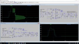
Zung, why would you obtain measured parasitic components and then use a simulation to determine an RC snubber across a secondary HT winding without also doing an in-situ measurement as per the quasimodo style ring test ?
Showing a scope screen without any description on what is being shown and what the test setup involved is imho just a waste of space.
No diode solution 'eliminates switching transients'. The issue is more about how a diode solution softens the forward current step transition when current reaches zero, and whether there is any aspect of reverse current recovery that may also occur.
Last edited:
Mark Johnson on diodes in Linear Audio Vol 10
Mark has generously shared Quasimodo with us (takes the guesswork out of snubbing, Zung) as well as a survey of transformer ringing to find the best (actually least-worst) diode available for a very affordable 3Euro (here: All articles | Linear Audio - thanks, Jan). Here's the Abstract to persuade you to part with your money:
(My emphasis).
Mark has generously shared Quasimodo with us (takes the guesswork out of snubbing, Zung) as well as a survey of transformer ringing to find the best (actually least-worst) diode available for a very affordable 3Euro (here: All articles | Linear Audio - thanks, Jan). Here's the Abstract to persuade you to part with your money:
Power transformer secondary ringing was measured with 48 different semiconductor diodes; ringing amplitude was 10-20X lower with the best diodes than the worst. They all rang, including Schottkeys and HEXFREDs. A 1R + 2C snubber directly across the secondary completely eliminated ringing in every case.
(My emphasis).
Somewhat like the quasimodo test setup, the diode test setup in that Linear Audio article forces a very high peak current through the DUT, which is likely not what people will experience in their power supplies, but which does accentuate the transient disturbance at diode turn-off and so makes observations more distinct to then characterise.
rectifiers distort secondary currents as a result of rectification.....
Thats true but only as far as the smoothing cap then its smooth after that.
Given there are sharp charging impulses every 100Hz anyway it isnt a problem.
- Home
- Amplifiers
- Tubes / Valves
- How to use solid state rectification the best way