this is better: http://www.fetaudio.com/wp-content/uploads/2003/09/Mu-Stage.pdf
That's a seminal paper, but that was written years before high-voltage depletion-mode MOSFETs became widely available (DN2540, IXCP10M45, etc.).
These were explored in Walt Jung's seminal 2007 paper on making CCSs with the then-new depletion mode MOSFETs.
CCS AudioXpress 2007 - [PDF Document]
These were explored in Walt Jung's seminal 2007 paper on making CCSs with the then-new depletion mode MOSFETs.
CCS AudioXpress 2007 - [PDF Document]
I was thinking about how subsonic booms could happen from inadequate decoupling between stages of a tube phono preamp even if the B+ is a super-low output impedance regulated supply. I wanted to believe that a stiff, regulated B+ would keep this from happening, so I could use fancy film caps for 'better sound'. So I tested the problem in LTspice.
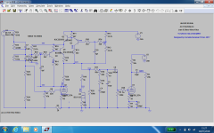
I have an RIAA preamp circuit worked up in an LTspice simulation, with a simulated Maida regulated B+ supply. It all runs fine and looks good. There is practically zero ripple on the plate supply.
The first (input) stage is a 6DJ8-LSK170 cascode, with an RC decoupling network of 2.2k ohms and 100uF for its plate supply.
The second (output) stage is a 6DJ8 with a DN2540 CCS in its plate, or a hybrid mu-follower. It has an RC decoupling network of 1.5k and 100uF for its plate supply.
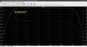
The frequency response is shown in the first attached graphic. As you can see, the response rolls off smoothly below 20Hz, just like we want it to.
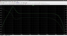
As an experiment, I reduced the 100uF decoupling caps to only 1uF. But... The Maida regulator's output impedance is like 2 or 3 ohms! It'll decouple everything all by itself, right? Well... No. The *audio* output frequency response with the 1uF caps in the decoupling networks is shown in the second attached graphic. As you can see, there's a big, fat BOOM centered right at 10Hz. Imagine what that would do to the cartridge/tonearm resonance! Wow. That's horrible.
I think what's happening is that the impedance phase reverses completely right at 10Hz. Since the amplifying stages invert, one is reversing 180 degrees and the other is reversing phase another 180 degrees again, to bring it back to 360 degrees (0 degrees) -- and now we have subsonic positive feedback. Argh. That's awful.
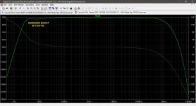
OK, what if I did the fashionable audiophile-approved thing and used 22uF metalized polypropylene caps in the decoupling networks? Won't that be enough? Well... The results are shown in the third attached graphic. As you can see, there's a shelf from about 3Hz to 6Hz where the response is close to 0dB (referenced to 1kHz) instead of being attenuated. That would cause unnecessary problems with footfalls, rumble, etc. Thoroughly marginal. Not good.
Thank you PRR for making this so clear to me.
--
I have an RIAA preamp circuit worked up in an LTspice simulation, with a simulated Maida regulated B+ supply. It all runs fine and looks good. There is practically zero ripple on the plate supply.
The first (input) stage is a 6DJ8-LSK170 cascode, with an RC decoupling network of 2.2k ohms and 100uF for its plate supply.
The second (output) stage is a 6DJ8 with a DN2540 CCS in its plate, or a hybrid mu-follower. It has an RC decoupling network of 1.5k and 100uF for its plate supply.
The frequency response is shown in the first attached graphic. As you can see, the response rolls off smoothly below 20Hz, just like we want it to.
As an experiment, I reduced the 100uF decoupling caps to only 1uF. But... The Maida regulator's output impedance is like 2 or 3 ohms! It'll decouple everything all by itself, right? Well... No. The *audio* output frequency response with the 1uF caps in the decoupling networks is shown in the second attached graphic. As you can see, there's a big, fat BOOM centered right at 10Hz. Imagine what that would do to the cartridge/tonearm resonance! Wow. That's horrible.
I think what's happening is that the impedance phase reverses completely right at 10Hz. Since the amplifying stages invert, one is reversing 180 degrees and the other is reversing phase another 180 degrees again, to bring it back to 360 degrees (0 degrees) -- and now we have subsonic positive feedback. Argh. That's awful.
OK, what if I did the fashionable audiophile-approved thing and used 22uF metalized polypropylene caps in the decoupling networks? Won't that be enough? Well... The results are shown in the third attached graphic. As you can see, there's a shelf from about 3Hz to 6Hz where the response is close to 0dB (referenced to 1kHz) instead of being attenuated. That would cause unnecessary problems with footfalls, rumble, etc. Thoroughly marginal. Not good.
Thank you PRR for making this so clear to me.
--
Attachments
i tried two hybrid versions of my own , and couldn't be more happier.the bipolar version although a bit too complicated for some.My first and realized verion was loaded with a a hybrid ccs(bc549 c+ 6n6p triode cascode), but until i simd it i didn't know that allan kimmel's additional loading wasn't really needed due to greater gm . The second version was based on bsp135 depletion mosfet ...That looked more like a gyrator, but had lower headroom.
Attachments
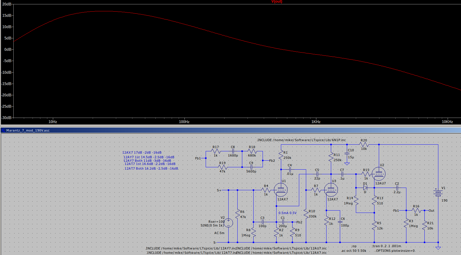
With regard to earlier discussion of 12AX7 Cmiller I suppose that if one has a passive phono stage then just popping in a 12AT7 or 12AY7 in the first stage would be worth a try at the expense of a little bit of gain. In a feedback implementation there would be loss of low bass output but it still might be worth a try. As an example I took a modified Marantz model 7 spice simulation that I have been playing with and substituted the above two tubes in 1st stage and both stages and got the following.
30Hz...1kHz...10kHz
12AX7s: 17dB -2dB -16dB
12AY7 1st: 14.5dB -2.5dB -16dB
12AY7 Both: 11dB -3dB -16dB
12AT7 1st: 16.6dB -2.2dB -16dB
12AT7 Both: 16.2dB -2.5dB -16dB
G-P capacitance mu
12AX7: 1.7pF 100
12AT7: 1.5pF 60
12AY7: 1.3pF 44
So for FB types 12AT7 has pretty small impact on bass response and would be worth trying first I think. 12AY7 is starting to make a likely quite noticeable reduction in low bass but has much lower capacitance. Again for a passive design I think that neither is likely to have a very noticeable impact on response just a drop in overall gain. Cheap and easy thing to try.
Funny you should mention that.... That's exactly what I'm doing today!
I've been meaning to try a pair of 12AT7 in the preamp. I have a lot of them saved up from my guitar amp repair days (LTP phase splitter in Fender amps).
I put the 12AT7s in with no changes, spun some records, and...
- There's absolutely no audible noise in the playback (other than record surface noise). No hum until I crank the volume up to 10. Even then the hum is low enough in level relative to the audio that I could use the preamp that way (if I really wanted to annoy the neighbors).
- Bass response is better. Tighter, more defined. Probably has to do with lower rp of the 12AT7 (about 20k ohms, I think).
- Level is lower, but with the lower hum+noise, perceived gain is a wash vs. 12AX7. With the 12AT7s in there, just crank up the volume a couple clicks with no noise penalty.
- My Audio Technica cartridge with max recommended load C of 250pF sounds good even with the full 47k loading. (It sounded too bright and strident with 12AX7 and 47k load, forcing me to lower the value of load resistor to 33k).
I think this is a success.
I have a spare pair of these audio PCBs, so I'm going to stuff them with an 'optimized for 12AT7' version of the audio circuits. LTspice predicts very good results, and still compatible with 12AX7. (12AX7 would have grid bias of only -1.1V, but I've seen lots of people use it that way in phono preamps.)
12AT7 operating points:
Input stage:
Ebb = 260V
Vp = 115V
Vg = -1.5V
Rp = 100k
Rk = 1k
Ck = 1000uF organic polymer
Ip = 1.5mA
Second stage:
Ebb = 275V
Vp = 125V
Vg = -1.6V
Rp = 100k
Rk = 1k
Ck = none
Ip = 1.6mA
LTspice predicts preamp gain of 41dB, frequency response very flat (-0.4dB at 20Hz).
How's that look?
Very cool Rongon. I don't have any ATs lying about but they are cheap enough. May play around with optimizing the first stage for AT and second for AX and see what can be done. IIRC I have some sort of AT cartridge on my TT too. In pushing for gain my sims have a pretty low plate current so I need to play around with operating points to see if I can get closer to the ideal noise current range.
Attachments
Thanks for sharing that. That's a pretty elaborate feedback EQ. I can't say I understand it, though!
I'm fiddling with the simpler all-in-one-go, passive Lipshitz EQ.
I didn't expect 12AX7s to be so sensitive to RF and low frequency instabilities. I suppose it's because they are such high impedance devices. Swapping in the 12AT7 instead of 12AX7 makes everything seem calmer—less noise, just better behaved. That's the exact opposite of the conventional wisdom, which says 12AT7 is prone to grid current and oscillation, and is generally noisy. Strange that I'm finding the opposite in this circuit.
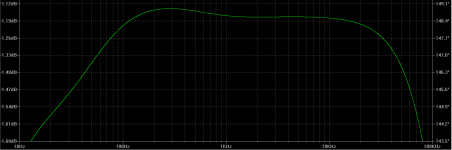
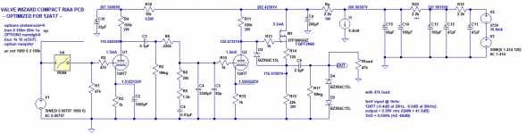
Here's the 'optimized for 12AT7' version of my passive RIAA circuit, along with the predicted frequency response (after inverse RIAA).
I'm fiddling with the simpler all-in-one-go, passive Lipshitz EQ.
I didn't expect 12AX7s to be so sensitive to RF and low frequency instabilities. I suppose it's because they are such high impedance devices. Swapping in the 12AT7 instead of 12AX7 makes everything seem calmer—less noise, just better behaved. That's the exact opposite of the conventional wisdom, which says 12AT7 is prone to grid current and oscillation, and is generally noisy. Strange that I'm finding the opposite in this circuit.
Here's the 'optimized for 12AT7' version of my passive RIAA circuit, along with the predicted frequency response (after inverse RIAA).
Attachments
Your circuit is quite interesting also. The one I am looking at is basically plagiarized from the Marantz model 7 and slightly adjusted for hopefully better drive capability and lower B+ (limited supply of power trannies on hand). I initially picked it because I have tons of 12AX7s of various types and I thought the FB type might be a bit more forgiving and independent of the particular tube condition and characteristics.
I have to go back to work next week so may be a while before the solder flies.
I have to go back to work next week so may be a while before the solder flies.
Another possibility that intrigues me is to use a medium mu triode (thus lower Cmiller) and a small signal pentode instead of two high mu triodes. There just happen to be several such things in a single bottle.
This is a picture of the idea based on the above Marantz circuit. Note this is not an actual design but just a picture of the idea.
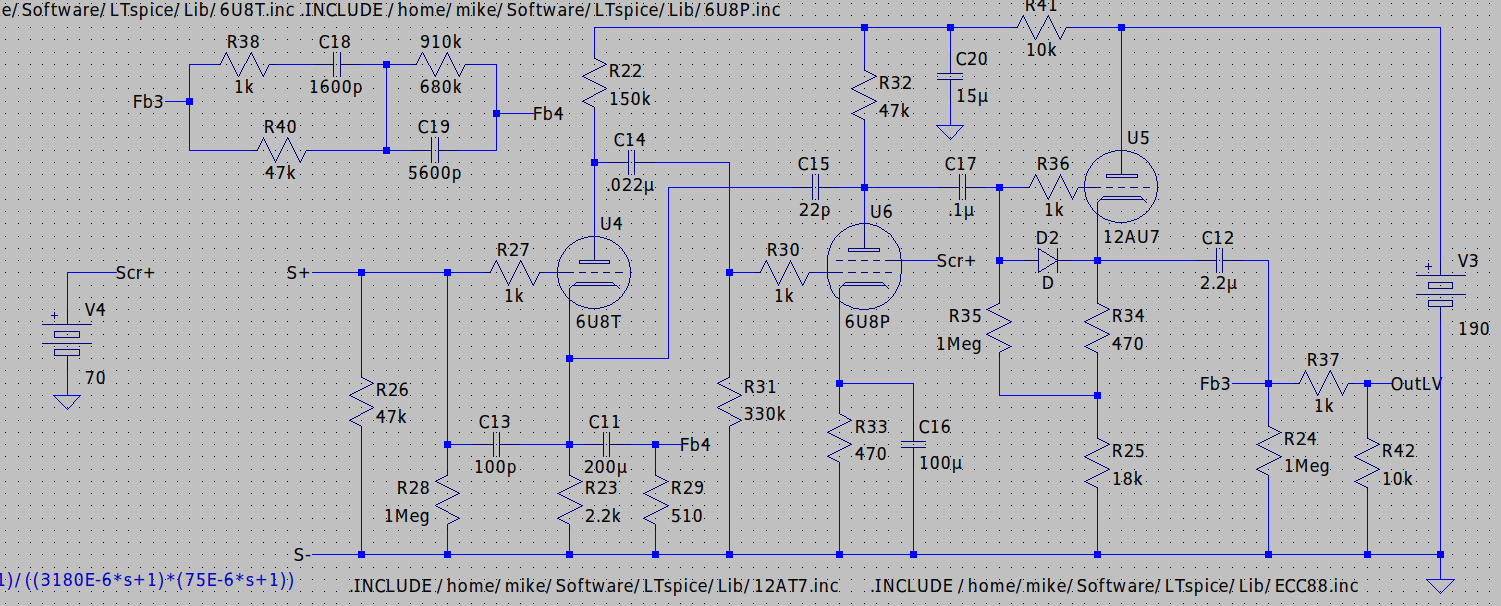
This is a picture of the idea based on the above Marantz circuit. Note this is not an actual design but just a picture of the idea.
Attachments
I wonder if the 'harsh' upper mids/trebles I heard from 12AX7s in this preamp are caused by the wheezy little 12AX7 triode trying to drive the gate capacitance of the MOSFET source follower?
I'm using an FQPF2N60 with Ids = 5.3mA for the source follower. Its Crss is listed as 4.3pF (5.6pF maximum). Let's say it's the maximum, 5.6pF.
In a DC-coupled source follower, that should equate to about 28pF Cin.
If we need to drive a 1V peak 50kHz signal into 28pF, that should require only 50uA (microamperes, 0.05mA). A 12AX7 with Ip = 850uA (over 15X the minimum requirement) should be able to sink that with no problems, so should not be anywhere near slewing driving a maximum 1V peak 20kHz signal.
Did I do that right? Is a 12AX7 OK driving the gate capacitance of an FQPF2N60 MOSFET source follower, or is it absolutely necessary to use a smaller MOSFET with ultra-low Crss like ZVN0545?
(The reason I ask is that I've noticed that the high frequencies sound far better if I put a 12AT7 in the same circuit. 12AT7 draws about 1.5mA, or almost double the plate current that a 12AX7 draws in that same spot.)
--
Last edited:
Another possibility that intrigues me is to use a medium mu triode (thus lower Cmiller) and a small signal pentode instead of two high mu triodes. There just happen to be several such things in a single bottle.
This is a picture of the idea based on the above Marantz circuit. Note this is not an actual design but just a picture of the idea.
Absolutely!
The trick is to find one with a low-noise, low Cin triode in the bottle with the pentode. Perhaps use the pentode as the input stage, triode second stage? Perhaps if the pentode is a very high-gm one, triode-wire it by grounding the plate and using the screen grid as the 'plate'.
People like to use the 6F12P for phono preamps, but the triode (and the trioded pentode section) have very high input capacitance.
Actually, there are many of those triode-pentode tubes that have something like a 12AT7 for the triode section. That works well enough, in my (newfound) experience because the 12AT7 has just low enough Cin to get by with an Audio Technica or similar MM cartridge. (I don't know about Ortofon 2M, but I figure that's similar to the AT carts in the L and DCR departments.)
--

I'm using an FQPF2N60 with Ids = 5.3mA for the source follower. Its Crss is listed as 4.3pF (5.6pF maximum). Let's say it's the maximum, 5.6pF.
In a DC-coupled source follower, that should equate to about 28pF Cin.
Why is that? Where does that factor of five come from?
Why is that? Where does that factor of five come from?
I think it's just 'headroom', or lots of slop factor so you don't end up running to close to the ragged edge.
I can't find the website where I read about slew rate limiting and how that relates to input capacitance of an amplifying stage, but the equation I got was
I = C * 2 * pi * F * Vpeak
Is that not correct?
I did the equation with 100kHz, not 50kHz. A mistake. (oops)
The result I get from 28pF Cin, 1.414V peak, and 50kHz audio signal, is 10uA plate current.
Therefore, I have to assume that slew limiting is not an issue with a 12AX7 with Ip = 800uA driving the FQPF2N60 source follower gate.
Now, my calculation of how to find the Cin of a MOSFET source follower might not be correct. I'm using
MOSFET source follower Cin = Crss + [Cgs(1-gain)]
therefore
5.6pF + [265pF(1-0.92)] = 26.8pF
(I wrote 28pF from memory, but it's close enough)
Correct?
--
Last edited:
It's amazing how a tiny change of value in the RIAA network can change the perceived tonal quality so much...
Using 12AT7 now in this preamp.
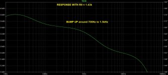
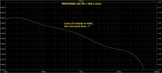
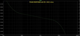
I had R9 as 1.43k, which according to LTspice will give a very slight boost to output in the 1kHz region.
I put 1k ohms in parallel with R9 to make 1.43k//1k = 588.5 ohms
- Predicted frequency response changes hardly at all in LTspice.
- Perceived change in tone quality on playback is that it's now much brighter, more emphasis on high frequencies. Could this be a result of changes in phase response?
Attached screenshots from LTspice
- Freq response R9 = 1.43k
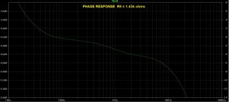
- Phase response R9 = 1.43k
- Freq response R9 = 588.5R
- Phase response R9 = 588.5R
It looks to me like the frequency response hardly changes at all, but the phase response in the 300Hz to 700Hz range changes a bit. Which one is more correct? The flatter phase response, or the phase response with a slight bump up at mid frequencies?
Are they both horrible? Or is this about what to expect from a passive 'all in one go' RIAA network?
--
Using 12AT7 now in this preamp.
I had R9 as 1.43k, which according to LTspice will give a very slight boost to output in the 1kHz region.
I put 1k ohms in parallel with R9 to make 1.43k//1k = 588.5 ohms
- Predicted frequency response changes hardly at all in LTspice.
- Perceived change in tone quality on playback is that it's now much brighter, more emphasis on high frequencies. Could this be a result of changes in phase response?
Attached screenshots from LTspice
- Freq response R9 = 1.43k
- Phase response R9 = 1.43k
- Freq response R9 = 588.5R
- Phase response R9 = 588.5R
It looks to me like the frequency response hardly changes at all, but the phase response in the 300Hz to 700Hz range changes a bit. Which one is more correct? The flatter phase response, or the phase response with a slight bump up at mid frequencies?
Are they both horrible? Or is this about what to expect from a passive 'all in one go' RIAA network?
--
Attachments
Last edited:
- Home
- Amplifiers
- Tubes / Valves
- For RIAA preamp: Large value caps vs. Regulated/Stabilized PSU