They are ham radio transformers. And as for being expensive, I consider two hundred bucks a bargain for a 1500VA, and a hundred a bargain for an 800VA. If you get half the watts in audio service it’s still a bargain. 1650W’s have gone up to over $400 and they only give 300 watts. Anybody else is going to want even more.Shoog: I think Antek makes (or at least used to make) mains toroids with some rather hefty HV secondaries, I vaguely remember seeing one with 2x750V windings on their homepage years ago. Probably quite espensive though. Ham radio transmitters also use very high voltages, that´s where I would look first for transformers north of a kilovolt.
The tube subwoofer amp part was mostly a joke,
Tube subwoofer amp is no joke. They weren’t a joke at Woodstock.
"Tube subwoofer amp is no joke. They weren’t a joke at Woodstock."
True. A high-GNFB pentode PP amp has more in common with a solid state amp than with a SET. My huge 75W PL519 monoblocks can drive pretty much anything and would probably work as spot welders too...")
Take a look at the Philips EL6471 for inspiration, a 1kW amp from 1955.
True. A high-GNFB pentode PP amp has more in common with a solid state amp than with a SET. My huge 75W PL519 monoblocks can drive pretty much anything and would probably work as spot welders too...
Take a look at the Philips EL6471 for inspiration, a 1kW amp from 1955.
Concerning the existence of mythical creatures… like the M&Ms and Santa Claus seeing each other. “They DO exist!”
OTOH, there is also a parallel path going on here - I’ve got a box full of both of the smaller ones, 20-0-20 and 30-0-30 that I bought surplus (for a song) maybe 25 years ago. More than I’ll ever use to build small solid state amps and therefore more expendable. Both lend themselves to running sweep tubes low and hot (in class AB, i like power) either singly or interleaved. Could also run massively paralleled 12W6’s.
OTOH, there is also a parallel path going on here - I’ve got a box full of both of the smaller ones, 20-0-20 and 30-0-30 that I bought surplus (for a song) maybe 25 years ago. More than I’ll ever use to build small solid state amps and therefore more expendable. Both lend themselves to running sweep tubes low and hot (in class AB, i like power) either singly or interleaved. Could also run massively paralleled 12W6’s.
Attachments
At least 10 years ago while I was still living in Florida, I found a bunch of toroidal power transformers in a dumpster. There were 3 designs each with it's own "Boca Systems" part number. There were two vendors for each part number for 6 distinct types of transformers. I also have about 8 160 VA Isolation / Power Filter transformers with 4 X 120 volt windings on each.OTOH, there is also a parallel path going on here - I’ve got a box full of both of the smaller ones, 20-0-20 and 30-0-30 that I bought surplus (for a song) maybe 25 years ago....... Both lend themselves to running sweep tubes low and hot (in class AB, i like power) either singly or interleaved. Could also run massively paralleled 12W6’s.
I tested all of them for use as P-P OPT's and came to some conclusions. Two transformers with the same part number on them, but made by different vendors can behave totally different from each other in OPT use. One of the largest (about 250 VA) was totally useless with a very lumpy frequency response in the 2KHz to 10 KHz range and severe rolloff above 15 KHz. The other was the best toroid tested as an OPT. All tests were done using E130L tubes at a relatively low voltage. Each toroid was tested with all possible combinations of primary and secondary windings for best performance. The larger 250 VA toroids have two 36 VCT and two 28 VCT secondaries, these are too high to be useful. These, and the 4 winding isolation transformers were tested with a new "secondary" wound through the core with hookup wire.
I also performed some parallel and massively paralleled vacuum tube amp experiments.
The first experiment used conventional OPT's or Plitron toroidal OPT's and 12 X 6AQ5 tubes. It ended with several melted 6AQ5's. I had over 1000 6AQ5's so I fried a few, OK, a lot. This experiment ran 6 paralleled 6AQ5's per side, each with it's own cathode resistor. All shared a common OPT. Several OPT's were tried including my pair of surplus 1250 ohm Plitrons rated for "400 watts @ 20 Hz." These OPT's also work well at 2500 and 5000 ohms at less than 400 watts. Current hogging was a problem. The amp would run, and make decent music, but within a few minutes one tube would go into a red plate runaway. These were all used tubes in unknown condition, though each pair had been tested in a single pair amp with good results and relatively well matched cathode voltages. I chalked this up to old unknown tubes.
I repeated the same experiment with NOS Sylvania 13GB5's. This worked better, but current hogging and some red plated tubes were still a problem. I did have an 8 tube version running for several days without incident.
I tried connecting a conventional E-I OPT to each pair of tubes then wiring the OPT secondaries in a series - parallel connection. Here I could get all 12 tubes to play nice with each other, even when wired in a fixed bias configuration. Some stupid amount of power flowed from this mess, but it was plagued by a random oscillation issue. The wiring was crude, and the OPT's were low buck surplus originally intended for guitar amps.
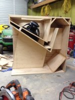
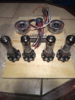
The next stupid experiment involved 8 of the 13GB5's with each pair driving one of the good 250 VA toroids with the primaries wired in series with the secondaries as described above. All four toroids were stacked on top of each other with a single "secondary" wound through all four cores. Note, test the "polarity" of each toroid with a single turn secondary before getting the whole stack built only to discover that one toroid is upside down. The 4 up stack of toroids worked pretty good. I originally was intending to use this in a guitar amp with 6 or 8 tubes surrounding the stack in a cabinet with a clear Lexan front. I tried wrapping some Electro Luminescent wire through the core along with the secondary and capacitively coupling the wire to the output tube plates. This made for some multicolored light effects that danced with the music. I was going to call this thing the Tubelab Sonic Reactor, available in 2, 3, or 4 cores. Add some red LED's under each output tube, and a good guitar player might even be able to achieve a "core meltdown." An illusion of course.
The sound quality of this "reactor" was good enough for HiFi until it was pushed hard enough for core saturation to be evident. The lowest frequency produced by a conventually tuned standard guitar is 82 Hz, so saturation is not an issue there. The fun ended when I learned that my career was over, and I would soon be leaving Florida. the 13GB5 tubes were on the dollar list at ESRC so I bought 100. I got a call from Stan at ESRC during these experiments. He offered to buy back the 13GB5's for $2 each in credit, so my "toy" tubes went away. A "US buyer" had bought every 13GB5 he had and wanted more. Tubelab was packed up and moved 1200 miles. I have the reactor in a box somewhere, maybe I'll get back to it someday, if I ever find it, I have better bigger tubes to fry now.
When Kodabmx posted about his favorite toroidal power transformers listed at a parts distributor for under $15 each instead of the usual $42 I bought 6 of them. Some experiments with them will occur and maybe I'll even build a new reactor.
Last edited:
Ya, I'm looking forward to that... I would be interested in seeing what you think of them...
I'm building another amp with four of those as OPTs this week.
BTW, I can send you a pair of my VA/PI/DR boards to play with, too. Send me your address and let me know if you need a pair of 6F12P to go with them, too.
I'm just thrilled by the performance TBH and think you'll like the results.
I haven't done many experiements with pentode, but trioded sweeps work very well (I also use automatic fixed bias boards so there's no hogging or runaway).
I've designed my sweep amps to run a voltage double/quad to get 320V/600V from a 120V coil as to keep costs down. 320V for the output stages, 600V for the VA/PI/DR boards. They will swing over 200Vpp into the triodes so EL509 and the like are easy. I use a -150V bias supply for big sweeps, and -75V for small ones.
That’s one of the reasons I’m not just jumping in with the 12 26LW6 driving the 1900VCT Antek - Get the bias servo working FIRST. That’s still in design/debug and unfortunately on the back burner till the new house/shop is built - and I’m still just getting bids. The “amplifier” part of it is no more difficult than anything else - I’m used to building SS amps with 20 power transistors per channel and tube-capable power supply voltage.
In the meantime there are more expendable tubes to play with. If/when I come across something worth taking to finished product I’ll pursue it. One of the current projects is just using 10CW5’s to drive run of the mill 6-0-6 volt power toroids. My version of the HBAC. Another is an all TV tube integrated amp with “regular” OPTs. Nothing likely to burn the shop down or be so all-consuming that it can’t be set aside for a while. And I managed to come up with enough of several different cheap sweeps to give those 20-0-20 toroids a go and see if I can get 200-400 watts out of a pair (of the toroids, using as many tubes as it takes). Although it might be fun to gang up a dozen or more 12W6 and see if it will do it too. All those cute little GT’s…. Probably enough filament power to heat the house in winter.
In the meantime there are more expendable tubes to play with. If/when I come across something worth taking to finished product I’ll pursue it. One of the current projects is just using 10CW5’s to drive run of the mill 6-0-6 volt power toroids. My version of the HBAC. Another is an all TV tube integrated amp with “regular” OPTs. Nothing likely to burn the shop down or be so all-consuming that it can’t be set aside for a while. And I managed to come up with enough of several different cheap sweeps to give those 20-0-20 toroids a go and see if I can get 200-400 watts out of a pair (of the toroids, using as many tubes as it takes). Although it might be fun to gang up a dozen or more 12W6 and see if it will do it too. All those cute little GT’s…. Probably enough filament power to heat the house in winter.
You'll find the LF is trash unless you use two interleaved, but I think I mentioned thatI actually got a bunch of PL509s as part of a tube lot on e-bay, and I will definitely try a 160VA toroid (2x115, 2x12) in push-pull to see how well it performs.
You did indeed 👍You'll find the LF is trash unless you use two interleaved, but I think I mentioned that
Thanks for the offer, but I have 5 different pairs of driver boards that are already built and working to play with. I still have a pair of unpopulated UNSET boards to hack up which will likely be the basis of the next round of push pull experiments.BTW, I can send you a pair of my VA/PI/DR boards to play with, too. Send me your address and let me know if you need a pair of 6F12P to go with them, too.
I haven't done many experiements with pentode, but trioded sweeps work very well (I also use automatic fixed bias boards so there's no hogging or runaway).
I've designed my sweep amps to run a voltage double/quad to get 320V/600V from a 120V coil as to keep costs down. 320V for the output stages, 600V for the VA/PI/DR boards. They will swing over 200Vpp into the triodes so EL509 and the like are easy. I use a -150V bias supply for big sweeps, and -75V for small ones.
All of the tests I mentioned in post #106 used pentode mode with some feedback applied. The UNSET / CED technology uses a pentode with direct plate to grid feedback to get triode curves. This allows feeding the sweep tube tube 600+ volts on the plate while keeping the screen grid happy at 150 to 175 volts. I have seen 250 watts flow from a single pair of 26LW6 tubes in this manner with the Plitron OPT at 2500 ohms on 625 volts.
If I get 250 watts from a single pair of 26LW6's, how much power are you expecting from 6 pair? Enough for Marty McFly's guitar amp, or enough to power the DeLorean back to 1985 (1.21 Jiggowatts)? In reality 250 watts per pair is possible for a typical music application, even a guitar amp. You could not build it for 250 watts then expect it to make a continuous 200 watt sine wave for ever though. Max dissipation occurs somewhere between half and full power for most class AB amps. the exact point is dependent on the bias conditions.That’s one of the reasons I’m not just jumping in with the 12 26LW6 driving the 1900VCT Antek - Get the bias servo working FIRST.
In the meantime there are more expendable tubes to play with. If/when I come across something worth taking to finished product I’ll pursue it. One of the current projects is just using 10CW5’s to drive run of the mill 6-0-6 volt power toroids. My version of the HBAC. Another is an all TV tube integrated amp with “regular” OPTs. Nothing likely to burn the shop down or be so all-consuming that it can’t be set aside for a while. And I managed to come up with enough of several different cheap sweeps to give those 20-0-20 toroids a go and see if I can get 200-400 watts out of a pair (of the toroids, using as many tubes as it takes). Although it might be fun to gang up a dozen or more 12W6 and see if it will do it too. All those cute little GT’s…. Probably enough filament power to heat the house in winter.
I get a new amp design working correctly with cheap expendable tubes first long before even thinking about using something hard to get or expensive. Stan (ESRC) sold be a box full of 6DG6GT's cheap because but nobody would buy them. They ARE a 6W6. I also god a box full of 6DB5's which are 9 pin 6W6's, and a bunch of 6GF5's for $1 each. These are all 10 watt sweep tubes. I got about 80 6BQ6GA's and 35 or so 6AV5's These were surplus at less than $1 each. These are the same electrically, but one has a plate cap, the other doesn't. The 6BQ6 was one of the tubes I learned on since they were available in discarded TV's. The 6DQ6 was a larger sweep tube also seen in 50's vintage TV's. I blew lots of these up as a kid. Today I can squeeze 100 watts from a pair at 3% THD without melting them. There are lots of different tubes with 6DQ6 guts in them. The 6GE5, 6JN6, 6GV5, 6JM6 are some of them and the previously mentioned 6GF5 is a 6DQ6 with its plate wings cut so it will fit in a tiny bottle. keep them down to 70 watts per pair. Many of these tubes are still cheap in odd voltage heater versions.
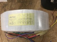
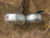
1. Use the 115+115V windings for the anodesI just "accidentally" ordered two rather phat toroid transformers from a surplus dealers. The more realistic option is to use them in a power supply for my almost-finished class A SS amp but I couldn´t help noticing their potential use as PP OPT´s with CFB windings.
Assuming a symmetrical 115+115V primary we should have a winding ratio of (115+115+37+37)/19 = 16, ignoring the low current 18 and 27V windings.
16^2*8 =2048 Ohms Ra-a, right in the ballpark for a pair of EL509 or maybe a quartet of smaller sweep tubes.
Worth a try, or should I put them in my SS amp right away?
The combination of big sweep tubes and a PP CFB topology would probably attract some interest from the God of Oscillating Amplifiers...and possibly from George at Tubelab too
2. Use the 37+37V windings for the cathodes.
3. Use the 18V winding for global feedback.
4. Make another 19V winding (with 1.2mm Cu-wire) and use it in series with the 19V winding for the loudspeaker.
5. The turns ratio prim:sek is now ca 304:38
6. The impedance ratio is now ca 64:1
No, not expecting enough power for the DeLorean - just in the neighborhood of a kilowatt. Starting with about 900 volts, I calculate a KW at 90% supply regulation and 800W at 80% regulation. Real world is usually somewhere between the two. I never think of amplifiers as how much “power” you Can get out of any particular “tube(s)” - I think of them the same as transistors - they are just modulators that you need to size for the task. The power is limited by how much you can cram through any given piece of IRON. The trafos are the ultimate impedance matching between the incoming 120V 60 Hz and the loudspeaker - they (both power and OPT) determine the available power. And you can’t add capacity except by buying or winding a bigger one. I have a transformer solution which will provide this - Antek 15T950 OPT, an a huge 480V (multi tapped for easy adjustment) industrial control trafo in series with a 1kVA 75-0-75 toroid for power. The idea is to put the two supplies in series, giving me a couple options for starting screen voltage. I may not need more than 110 volts there since the peak currents in each LW6 will be under half an amp, but I can put that as high as 220 easily and I know it won’t need any more than that. The 26V heater winding can be slapped on top of the toroid. I have plenty of magnet wire.
For a typical loaded supply of 800V (90% regulation - unlikely this high) power dissipation in this rig would be 256 watts per side, or 43 watts per tube at the 2/3 power point where dissipation is maximized. There IS an explicit formula for this - (B+^2)/(pi^2*R), which reduces to (B+^2)/(2.5Ra-a). Id have to keep the quiescent current at about 40 mA per tube (at the full 900V) to have lower dissipation at quiescent. Hoping the gm will be high enough down there - there are no curves to look at on the LW6. It was when playing with 26DQ5’s at 500V - they were happy at 30 mA.
What I need to figure out is a bias servo that keeps the average current balanced between the two banks, and at least MONITORS the dynamic balance within a bank - with the goal of controlling it. I’ve got a batch of 21EX6 to play with on lower voltage with the 8T800 as an OPT, then on the real supply and OPT to get this part developed. Run it on 8 ohms to get half the power (and dissipation, letting me use 23W tubes). Until I’m satisfied that things can be kept in balance, the LW6’s stay in their boxes. As with large solid state amps - designing and building the supervisor circuit is 90% of the work. And you don’t deploy one in the field without.
There are many schemes for this, but I prefer the Pavel's AB-4 from Audioamp.eu - That is, if you're looking for a turn-key solution. https://www.audioamp.eu/module-ab-4...he-amps-circuit-with-ttl-error-signal-output/What I need to figure out is a bias servo that keeps the average current balanced between the two banks, and at least MONITORS the dynamic balance within a bank - with the goal of controlling it.
If uses external 10R sense resistors (good when there's high currents in the amp). I would also upgrade the 100µF/25V caps to something longer lasting. I've had one or two dry up but it didn't seem to effect the biasing.
You can use more than -130V bias - I use 200V regulated to 150V by VR tube - AFAIK the SS parts are 400V (besides the JFET opamps (TL082). If you tend to blow the opamps with static, overloads, shorts etc Pavel will make you boards using socketed DIP-8 versions.
Last edited:
Output power (at 20 Hz): 58W RMS with an 4 ohm load and 29W with an 8 ohm load.1. Use the 115+115V windings for the anodes
2. Use the 37+37V windings for the cathodes.
3. Use the 18V winding for global feedback.
4. Make another 19V winding (with 1.2mm Cu-wire) and use it in series with the 19V winding for the loudspeaker.
5. The turns ratio prim:sek is now ca 304:38
6. The impedance ratio is now ca 64:1
125 ohm effective load in class AB, 250 running class A. Quite low, but you’re only going to be able to hit it with 170 volts peak (at 50 Hz, less if you want 20 or 30 Hz operation). This is within the capability 2 pairs of fat sweep tubes. Don’t try it with 6L6’s (Unless prepared to buy a lot of them - at today‘s prices).
I would say 215V peak @50hz when the 2x37V winding is used for cathode feedback. I can´t recall the exact numbers but IIRC the big transformers where good for about 25W @ 30Hz or something like that. They played rather well along with a pair of PL519 and 8R loads on the 19V windings for ~2k p-p. I think the latest revision used 330R cathode resistors, 320V B+ and 200V or so on the screen grids, effectively forming an UL output stage with quite a bit of local feedback thanks to those 37V windings. I also remember trying fixed bias, which allowed a lot
more power in class AB.
I have a personal preference for high eff. speakers and class A amps
more power in class AB.
I have a personal preference for high eff. speakers and class A amps
Many amp builders, especially guitar amp builders fail to realize this. They also don't realize that repeated venturing into saturation kills output tubes. I want to build a 1 KW tube amp, just because I can. It will be 500 WPC since my surplus Plitron OPT's are clearly marked "400 Watts @ 20 Hz" and I have seen 500 watts go through them at 30 Hz. The power supply is still undecided but I'll need 625 to 650 Volts at nearly 3 Amps. This amp will not be used for constant duty high power, so I don't need 3 amps continuously. I am nearly 70 years old so size and weight of this amp is a major design constraint, far above continuous power output capability. Heater power will likely be SMPS.The power is limited by how much you can cram through any given piece of IRON. The trafos are the ultimate impedance matching between the incoming 120V 60 Hz and the loudspeaker - they (both power and OPT) determine the available power. And you can’t add capacity except by buying or winding a bigger one.
That formula is a generalization assuming a typical idle current. If the amp runs in pure class B, then there is no plate dissipation at idle. Peak power dissipation occurs near the 2/3 power power point, provide it is driven to saturation at clipping. If the tube is biased in pure class A, worst case dissipation occurs at idle. Peak power dissipation in class AB depends on where the idle current is set, and where the knee voltage of the tube lies in relation to the supply voltage. A high purveyance TV sweep tube can pull its plate down to 30 volts or so even at high plate currents. A 6L6oid cannot, so it will be lossier in saturation unless driven hard into AB2 where it still won't be as good as a fat sweep tube. This tends to move the point of peak dissipation closer to max power. Circuit losses, especially in the OPT also are a factor. One must also consider the fact that maximum power output in a sweep tube amp is often dictated by the screen grid dissipation, not the plate. This point also moves with the load impedance. I typically make a spreadsheet that finds the point of maximum plate efficiency for a given tube and OPT impedance during my initial amp investigations.For a typical loaded supply of 800V (90% regulation - unlikely this high) power dissipation in this rig would be 256 watts per side, or 43 watts per tube at the 2/3 power point where dissipation is maximized. There IS an explicit formula for this - (B+^2)/(pi^2*R), which reduces to (B+^2)/(2.5Ra-a). Id have to keep the quiescent current at about 40 mA per tube (at the full 900V) to have lower dissipation at quiescent.
This spreadsheet shows some testing on two pair of 50C5 tubes operated well above their published voltage and plate dissipation ratings. I assumed an arbitrary 10 watt dissipation limit for the 50C5 since it's plate is actually larger than the 12 watt plate in the 6AQ5. The maximum screen grid dissipation is the limiting factor and is 1.25 watts. Two sets of tubes were tested one Sylvania, and one RCA. B+ is 340 volts and Vg2 is 150 volts. Idle current was set at 15 mA. In both cases the peak dissipation occurs at about 15 watts of output. One set hits maximum G2 dissipation at 26 watts of power output but the other set can go to 31 watts of power output before overdissipating the screen grid. In both cases the point where THD hits 3% is the point where G2 dissipation hits max spec. The 50C5 is derived from the 6W6 and does behave like a sweep tube. Its tiny size makes it easy to kill, but paying attention to screen current can allow for maximum power extraction. I find that this is often the case with sweep tubes from small to large.
I set the maximum power output for a test amp at 20 watts by limiting the screen current. This puts maximum plate dissipation very close to maximum power output. The test amp successfully ran for about 10 hours at 20 watts with no issues. Power was 20.02 watts after 10 hours.
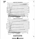
Someone emailed me some 6LW6 curves. I also made some pulsed tests for areas not explored in the data sheet in the PDF......up to 600 watts of dissipation for 1/2 second!there are no curves to look at on the LW6. It was when playing with 26DQ5’s at 500V - they were happy at 30 mA.
What I need to figure out is a bias servo that keeps the average current balanced between the two banks, and at least MONITORS the dynamic balance within a bank - with the goal of controlling it. I’ve got a batch of 21EX6 to play with on lower voltage with the 8T800 as an OPT, then on the real supply and OPT to get this part developed. Run it on 8 ohms to get half the power (and dissipation, letting me use 23W tubes). Until I’m satisfied that things can be kept in balance, the LW6’s stay in their boxes. As with large solid state amps - designing and building the supervisor circuit is 90% of the work. And you don’t deploy one in the field without.
keeping the bias in check and watching the screen current for each output tube in a big power amp is mandatory. Even the purpose built Plitron toroidal audio output transformers get upset by mismatched currents from side to side. I plan to use an Arduino compatible controller with an LCD display for keeping an eye on this amp. Cathode and screen current at idle, and under power will be watched by the "main brain." Limiting and shutdown features will be implemented, since Plitron is gone and there are no more of these OPT's. This can be expanded as needed during initial testing.
Attachments
Last edited:
- Home
- Amplifiers
- Tubes / Valves
- Surplus toroid transformers as OPTs...with a little twist.