Let´s see what we have here:
220R in series with the 2*115V primary winding (CFB winding not connected) drops 2,5V at 230V 50Hz with open secondaries, which gives 2,5/220 = 0,0114A no-load current.
XL=U/I= 20175
XL = 2*pi*f*L
L = XL/ (2*pi*f) = 64H
I´ts been 25 years since I read AC theory in high school, I´m probably missing something important here...
L = XL/ (2*pi*f) = 64H
I´ts been 25 years since I read AC theory in high school, I´m probably missing something important here...
This sounds more realistic, for a good 50/60Hz transformer.With all secondaries shorted I get 1,25mH across the primary, measured with the LCR meter.
But this makes you realize that the large ratio between the small-signal inductance and the amplitude inductance will cause an awkward transition somewhere in the open-loop transfer function.
(NB: the leakage inductance is practically unaffected by the core properties)
If you measured right those power transformers would beat the majority of output transformers")
64H is unbelievable high for a power transformer , because of the very low current .
Leakeage inductance is very low too.
The data I got when I reached out to Triad as I build using PTs as OPTs
"The following data is from Triad magnetics.
"Inductance depends on the drive level and the permeability of the core (which can vary significantly). Having said that, I have reviewed some history data from various lots and here are the results.
1. VPT230-110 = 213 to 439H @ 230V, 50Hz (primaries in series). 304H average from 15 samples.
2. VPT230-220 = 192 to 444H @ 230V, 50Hz (primaries in series). 283H average from 15 samples.
3. VPT230-430 = 93 to 214 @ 230V, 50Hz (primaries in series). 128H average from 15 samples."
The same applies for the rest of the VPT series, as the primary is the same."
Yes, transformer inductance seem to vary all over the place depending on signal level and frequency. AFAIK air gaps makes the inductance much more constant but there are none in toroids.
The primary inductance was measured without the CFB winding, adding this should increase the inductance to ~100H. I guess the leakage inductance will increase too, though.
BTW: These transformers are probably closer to 400VA than 250. The high-current winding is wound with 2,25mm wire
The primary inductance was measured without the CFB winding, adding this should increase the inductance to ~100H. I guess the leakage inductance will increase too, though.
BTW: These transformers are probably closer to 400VA than 250. The high-current winding is wound with 2,25mm wire
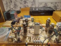
Made a new breadboard with a better power supply* and a 12AT7- based LTP phase splitter. Results:
Clipping just below 40Vpp @ 7,5R load, and I have reasons to believe that the phase splitter runs out of juice before the output tubes.
With zero GNFB I'm 1dB down somewhere around 25Hz at full power and the HF irregularities went away with the LL1660, now it's pretty much flat past 50kHz. Not bad, not bad at all!
* The new PSU is still not big enough to run the tubes att full power, ie 35W each. Currently I run them at 280V 73mA each, with fixed bias.
Last edited:
Looking good !
If you are curious about the low frequency power capability, a simple frequency sweep won't show you that. I've tested power toroids as output transformers by choosing the lowest frequency of interest (e.g. 30 Hz) then gradually increasing the output level while monitoring distortion using REW (just need a computer with a decent sound card and the free software). You will see distortion slowly rising with output level as normally expected, but when you approach saturation the distortion rises very rapidly with nasty looking distortion profile.
Alternatively you can pick the maximum desired output power then slowly lower the frequency until you see the sudden rapid rise in distortion indicating saturation.
!If you are curious about the low frequency power capability, a simple frequency sweep won't show you that. I've tested power toroids as output transformers by choosing the lowest frequency of interest (e.g. 30 Hz) then gradually increasing the output level while monitoring distortion using REW (just need a computer with a decent sound card and the free software). You will see distortion slowly rising with output level as normally expected, but when you approach saturation the distortion rises very rapidly with nasty looking distortion profile.
Alternatively you can pick the maximum desired output power then slowly lower the frequency until you see the sudden rapid rise in distortion indicating saturation.
Thanks
I´m getting inconsistent results on the LF behaviour from different iterations of this prototype. Right now the tubes are running at 325V 60mA each (fixed bias), resulting in 48W in out class AB but with ugly waveforms below 35Hz.
This may or may not be the result of DC imbalance, my bias supply is a bit "shaky" to adjust...
Since I would probably be happier with a 20-25W class A amp than with a 50+W AB ditto, I think I will give cathode bias another chance now that I have a power supply that can cover for the voltage lost in the cathode resistors.
Cathode bias allows higher value grid leaks which puts less strain on the driver stage/phase splitter, definitively a good thing in an amp with 25% CFB.
Cathode bias should also help with the DC balance (though some way to fine-tune the bias is probably necessary) and offer some protection against Chernobyl-esque scenarios if/when something goes wrong. These tubes can pull way over 1A each from my 500VA power transformer at zero bias...
Not my traces, but when I used only one transformer, I got waveforms like this (in yellow) for LF due to core sat in relation to voltage and frequency.
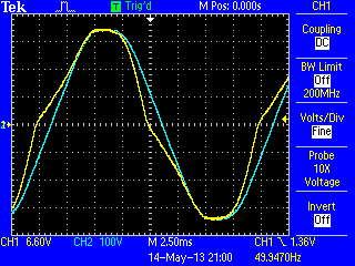
I would get 100W at 50Hz, but only 14.7W at 30Hz. before it started to look like the yellow traces above.
Since I started "Interleaving" two coils, I get full power at 30Hz.
I would get 100W at 50Hz, but only 14.7W at 30Hz. before it started to look like the yellow traces above.
Since I started "Interleaving" two coils, I get full power at 30Hz.
Toroids tend to have lower leakage inductance than EI’s for a given VA rating when it comes to power transformers. With toroids you tend to get frequency response into the upper octave of audio (or beyond) without taking any special steps in the design or winding process. There are only one or at most two layers of turns on each winding for a power toroid, but they usually are bifilar. Primary and secondary are just concentrically wound. Similar construction technique on an EI would only give you response to a couple kHz and drop like a stone. With more magnetic leakage paths available, and longer wires to give more capacitance, more attention must be paid to get a given upper corner frequency. It’s a don’t care at 60 Hz. But there is more to transformer sound than just the upper and lower corner frequencies. The quality of the core and how hard it’s being driven have an impact on distortion and loss across the entire band. That varies all over the place on power transformers, and no power trafo manufacturers will ever use some of the exotic materials that audiophile output trafos have been known to use. You do tend to get what you pay for. Trafos that would sound “good” tend to run cool in power applications. So if you’ve got one that runs hot and buzzes a lot when just left plugged in with no load, it probably wouldn’t be a good choice for an OPT.
Shoog:
Will try. So far I´ve always had the transformer connected in the same way but with different results depending on bias, plate voltage and DC balance.
kodabmx:
That yellow waveform looks familiar, this is what happened below 35Hz yesterday. Previous, lower power versions of this amp has shown the same behaviour at lower frequencies, 20Hz or so (I don´t remember the exact numbers for every iteration).
More tests to come.
jxdking:
Last time I checked the HF was dead flat up to 50kHz, which is the limit of my tone generator
Toroids tend to have lower leakage inductance than EI’s for a given VA rating when it comes to power transformers. With toroids you tend to get frequency response into the upper octave of audio (or beyond) without taking any special steps in the design or winding process. There are only one or at most two layers of turns on each winding for a power toroid, but they usually are bifilar. Primary and secondary are just concentrically wound. Similar construction technique on an EI would only give you response to a couple kHz and drop like a stone. With more magnetic leakage paths available, and longer wires to give more capacitance, more attention must be paid to get a given upper corner frequency. It’s a don’t care at 60 Hz. But there is more to transformer sound than just the upper and lower corner frequencies. The quality of the core and how hard it’s being driven have an impact on distortion and loss across the entire band. That varies all over the place on power transformers, and no power trafo manufacturers will ever use some of the exotic materials that audiophile output trafos have been known to use. You do tend to get what you pay for. Trafos that would sound “good” tend to run cool in power applications. So if you’ve got one that runs hot and buzzes a lot when just left plugged in with no load, it probably wouldn’t be a good choice for an OPT.
With toroidals parasitic inductances are negligible and can be safely ignored. The real limitation is parasitic capacitances which the manufacturers pay almost no attention to. These have two effects - they can couple the high frequency signal from the primary to the secondary, which will produce a rising response but which generally compensates for the otherwise falling response. The more critical parasitic is the is the capacitive-inductive tanks which can produce significant high frequency ringing - serious enough to saturate the core and produce large LF distortion as a secondary consequence. How you wire up the primaries will effect the degree of these parasitic capacitances.
Shoog
I ran some quick tests with my vintage tone generator and oscilloscope, so take the results with a grain of salt:
At 26V peak into 7,5R (45W) the waveform starts to get visibly distorted at 40Hz, 30Hz at 20 Vp (~27W) and 22Hz at 15Vp (15W). Tweaking the DC balance has no visible effect on the distortion.
This leads me to the conclusion that these transformers can be used in a hifi amp up to maybe 20-25W (ie no point in designing for class AB) OR in a mammoth sized guitar amp.
BTW, yesterdays not-very-critical listening test went fine, no complaints.
Time to change back to cathode bias and see how the circuit can be optimized.
- Home
- Amplifiers
- Tubes / Valves
- Surplus toroid transformers as OPTs...with a little twist.