There does not appear to be any method to sense (and no method to adjust the cathode current of the individual output tubes to be equal).
It is important to balance the plate currents.
Assuming the screen currents are equal if the plate currents are equal, then you can sense the cathode currents with individual 10 Ohm cathode resistors to ground.
Or sense the plate current instead of the cathode current, with individual 10 Ohm resistors from the plates to the primary windings, and the screen currents will not affect that reading.
Were the two 500 square wave traces with and without NFB, or were those the two square waves of two channels?
The 500Hz square wave might look that way because of:
Unbalanced plate currents, and the core is in saturation during one polarity direction of the square wave.
Or, the tubes are extremely un-matched in gain.
I have the belief that using Toroid Power transformers as output transformers works very well for 3 categories of builders:
1. Seasoned Designers
2. Builders who meticulously copy a well woking design, including exactly all the same parts.
3. Those who will experiment, often with help of 10s or 100s of posts in a thread.
If by chance there is a #4, it is by 'Sheer Luck' (Feeling Lucky? Put your money on the table at Las Vegas).
Others will not use Toroids as output transformers.
If an amplifier design is struggling to have good or at least reasonable looking square waves into an 8 Ohm load resistor, how stable will that amplifier be into a loudspeaker?
Just my opinions
Last edited:
There does not appear to be any method to sense (and no method to adjust the cathode current of the individual output tubes to be equal).
It is important to balance the plate currents.
Assuming the screen currents are equal if the plate currents are equal, then you can sense the cathode currents with individual 10 Ohm cathode resistors to ground.
Or sense the plate current instead of the cathode current, with individual 10 Ohm resistors from the plates to the primary windings, and the screen currents will not affect that reading.
Current has to be measured at the plate, because both plates share a single cathode. On the breadboard, I'm measuring with an inline ammeter at each plate. Balancing is handled by individual bias per side.
Were the two 500 square wave traces with and without NFB, or were those the two square waves of two channels?
Only the last trace was at 500Hz. The second to last was 1kHz, which while obviously not perfect, is at least symmetrical.
The 500Hz square wave might look that way because of:
Unbalanced plate currents, and the core is in saturation during one polarity direction of the square wave.
Or, the tubes are extremely un-matched in gain.
I suspect it's more related to the transformer, because it's dependent on frequency, not amplitude. The 1kHz square wave makes it through relatively unscathed, but the lower frequency is where the weirdness happens. I'll sweep it this evening and see where it actually goes sideways.
I have the belief that using Toroid Power transformers as output transformers works very well for 3 categories of builders:
1. Seasoned Designers
2. Builders who meticulously copy a well woking design, including exactly all the same parts.
3. Those who will experiment, often with help of 10s or 100s of posts in a thread.
If by chance there is a #4, it is by 'Sheer Luck' (Feeling Lucky? Put your money on the table at Las Vegas).
Others will not use Toroids as output transformers.
If an amplifier design is struggling to have good or at least reasonable looking square waves into an 8 Ohm load resistor, how stable will that amplifier be into a loudspeaker?
Just my opinions
That's all fair. I'd put myself in the #3 category at best. Others have reported success using the primary scheme described by kodabmx, and it makes sense from a logical POV, so I thought I'd give it a try. Worst case scenario, I'm out a few bucks and have to go buy real OTs.
Defen, it can be easier to interpret operation, and set up the circuitry, without feedback connected. Waveforms internal to the amp circuit, when there is GNFB, will get quirky especially where signal levels are large and squarewave style. Until you have the circuitry correctly set up (eg. balanced output stage idle cathode currents, and tube-rolled to get balanced gains and min distortion, and mid-point biasing of PI stage) then its uncertain what is being observed when large signal levels are applied.
I'd anticipate your sim is not sufficient to reasonably determine gain and phase margins with feedback applied. Do you have any measurement equipment to better appreciate gain and phase of the amp to out past where the amp with feedback will unity cross at each end of the spectrum?
I'd anticipate your sim is not sufficient to reasonably determine gain and phase margins with feedback applied. Do you have any measurement equipment to better appreciate gain and phase of the amp to out past where the amp with feedback will unity cross at each end of the spectrum?
1. I agree with trobbins, removing negative feedback and using small amplitude square waves can reveal problems with the bare bones circuitry.
2. An old rule of thumb rough approximation said that if a square wave looked pretty good, you had flat frequency response from 0.1 x the square wave frequency to 10x the square wave frequency.
1kHz square wave, 100Hz low freq.
500Hz square wave, 50Hz low freq.
The difference between 100Hz versus 50Hz on an output transformer could be:
non-saturated, versus saturated (especially if there is global negative feedback).
Sometimes with saturation and negative feedback, the NFB can cause sticking.
And with un-balanced quiescent DC, or with un-balanced AC gain of the output tubes, the transformer can be saturated in one direction, but not the other.
Last edited:
Defen, it can be easier to interpret operation, and set up the circuitry, without feedback connected. Waveforms internal to the amp circuit, when there is GNFB, will get quirky especially where signal levels are large and squarewave style. Until you have the circuitry correctly set up (eg. balanced output stage idle cathode currents, and tube-rolled to get balanced gains and min distortion, and mid-point biasing of PI stage) then its uncertain what is being observed when large signal levels are applied.
That's a great point, and something that I neglected until later in the process of dialing it in. I was focused on getting maximum power, and figured I'd work on sonics afterwards. I now see that that was the incorrect approach!
It's set up for full output (1kHz, <2% THD) at 1Vrms in with feedback applied. I've been doing my square wave tests with 500mVrms, but still with the feedback in place. Next chance I have to sit down with it for a couple hours, I'll remove the feedback and start over with something more like 100mVrms.
I'd anticipate your sim is not sufficient to reasonably determine gain and phase margins with feedback applied.
Oh, for sure! Earlier upthread there was a discussion on the fact that simulation can only take one so far, especially with components that have less-than-perfect models. That's why I only worked with LTspice until I got to a topology and ballpark component values, then built it for real.
Do you have any measurement equipment to better appreciate gain and phase of the amp to out past where the amp with feedback will unity cross at each end of the spectrum?
With the scope, I can see and measure gain, and see phase shift for one frequency at a time. And, I suppose, if I *have* to use math (ugh), I can measure the phase shift too. I also use the scope for THD measurements, by manually measuring harmonic levels on the FFT and using this tool. I just can't justify the cost of a distortion analyzer for the few projects I do.
My function generator is rudimentary, but I ordered one that can do sweeps from Banggood and it will hopefully arrive sometime this decade.
I would try to get rid of C1 before continuing the experiment. Not a huge redesign effort. It can probably be made to work with ac coupling but why start the game with one strike against you?
Now that I've got it built out I should give that a shot. I couldn't get it to simulate properly with DC coupling. It would never bias up right - couldn't get the cathode above the grid and still have any useful room left to swing. A shortcoming in the model for the tube, I'm sure. Considering it's basically a 12AX7 into a 6SN7, there's no reason it should be difficult at all. I mean, that was pretty much a solved problem by 1950, right?
1. I agree with trobbins, removing negative feedback and using small amplitude square waves can reveal problems with the bare bones circuitry.
Heard loud and clear.
2. An old rule of thumb rough approximation said that if a square wave looked pretty good, you had flat frequency response from 0.1 x the square wave frequency to 10x the square wave frequency.
1kHz square wave, 100Hz low freq.
500Hz square wave, 50Hz low freq.
Good to know! I vaguely remembered something like that, but couldn't remember it.
The difference between 100Hz versus 50Hz on an output transformer could be:
non-saturated, versus saturated (especially if there is global negative feedback).
Sometimes with saturation and negative feedback, the NFB can cause sticking.
And with un-balanced quiescent DC, or with un-balanced AC gain of the output tubes, the transformer can be saturated in one direction, but not the other.
Makes perfect sense. Quiescent DC is definitely balanced. For AC gain, I'm not sure how I would check one against the other, because the voltage across the primary is swung by both tubes. I guess I'd need to set up a jig that ran each side single-ended? Wouldn't be difficult, I've already got some 5K SE OTs, and my function generator can push up to 40Vpp so I wouldn't even need a driver.
Side note - I've been talking about the wrong frequency - the final trace was at 200Hz, not 500. I'm not expecting any kind of performance at 20Hz!
And hey, thanks so much for your advice on this. I really do appreciate it.
Although one often doesn't have to initially worry about instability, it should be a concern that you need to address based on measurement and that often means adding to your tool inventory and experience.
Can your scope do X-Y plot, as that is the simplest way to assess phase shift at really low and high frequencies - assuming your existing or new generators can get down to at least 1Hz and up to a few hundred kHz with sinewave.
I'd strongly recommend starting to use the soundcard and PC software path for basic audio design/measurement/assessment as well. It allows frequency response and spectrum, and distortion assessment within the bounds of the soundcard you have available. The frequency range will be limiting, but you have a scope and separate generators that should be able to acquire extended data when needed. Lots of threads on this forum - especially in Equipment-tools and Software tools sections.
I would try to get rid of C1 before continuing the experiment. Not a huge redesign effort. It can probably be made to work with ac coupling but why start the game with one strike against you?
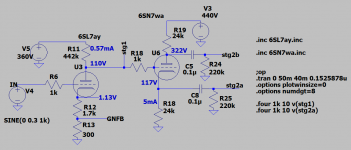
Okay, I got something going with this. However, in order to get U1's plate low enough to get useable bias between U2's cathode and grid, I had to put in a divider to ground. (Putting a divider to the cathode ala Merlin's example didn't work for multiple reasons.)
Because that divider is throwing away a bunch of signal as well, I had to increase the plate resistor and partially bypass the cathode on U1 to get enough swing. That does add some distortion, but the additional gain would allow more GNFB, so if I can avoid instability that works.
I haven't seen this construction elsewhere, so I'm assuming there's some reason it's a bad idea. However, it is working both in my prototype and in LTspice. Is this bad?
Idle voltages:
U1 Va=158
U1 Vg=0
U1 Vk=1.20
U2 Va=239
U2 Vg=106.5
U2 Vk=110.8

No, you don't have to throw away gain like that. You should be able to find a low distortion operating point for 6SF5 with the plate at somewhere around 100-125V and that will work just fine into a 6SN7 concertina.
Here is a similar circuit I tried a while ago, low distortion and no gain thrown away. Somewhere around 0.1%thd @ 30Vpp output. I've obtained similar results with 6SF5, just don't have a schematic handy right now.
Here is a similar circuit I tried a while ago, low distortion and no gain thrown away. Somewhere around 0.1%thd @ 30Vpp output. I've obtained similar results with 6SF5, just don't have a schematic handy right now.
Attachments
Been super busy with starting a new job, so this languished for a while. Good news and bad news ...
The good news is that I was indeed able to direct couple the concertina. It took a 390k plate resistor on the input stage to get the grid low enough.
The bad news is that I'm figuring out why the guy who sold me these was so generous and actually threw in two extra: they're all over the place, operating-point-wise. Some are weak, some have mismatched halves, and some are both.
I set up a test rig with 400V plate and 250V screen, then measured what bias voltage would result in 29mA idle current for each half. Per the datasheet, bogey is -20V.
Three were well-matched and reasonably close to target: 22/22, 19/19, and 18/18.
Two had moderate mismatches; one was hot (26/22) and one was very weak (13/9).
One was laughably mismatched: 21/9.
I'm going to do testing under load tomorrow.
All of the tubes that were matched at idle were also matched at full bore. Didn't bother to test the others. Maybe I'll throw together a guitar amp or something ...
That said, I made a few more tweaks - brought the screens back up to 275, changed the input stage load resistor to 430k, and adjusted the power stage grid resistors to get grid resistance down to 100k (the temporary bias supply adds a fair amount of resistance), and adjusted the NFB (which decreased the input sensitivity a bit). It now makes just over 20W at 0.7% THD on a 2Vpp input.
I remembered that I had a spare PT from an old Wurlitzer organ that should work well. With a tube rectifier it should provide a little more than enough voltage to safely regulate both B+ and screens (MOSFET series regulators, referenced to OB3s), but not so much that I have to worry about heatsinking the MOSFETs. It's got heater current galore - 5V@3A, 6.3V@6A, and 12.6V@4.3A ... the organ had 2x7868, 9x12AX7, and 29x12FQ8. Plus three 6EU7s and a 6CB6 in a separate chassis. And, for once, I've got a bias winding!
This weekend I'll rig up the second channel and start getting the power supply in shape. Onward!
Second channel all built. Ran into a minor hassle because I jumbled up the OTs' cross-transformer primary connections. That cost me like two hours as I tried to figure out why things went all wonky when I hooked up the GNFB, even when I swapped sides. Finally figured it out around 1 AM, go figure.
Now it's time to see about gain staging with a real signal. My test CD player has a nominal 2.8Vpk output, but I'm seeing plenty of peaks above 3.5V, even a few kick drum transients around 5V. So on the one hand, good on Samsung for having lots of dynamic range, but on the other, boo on Samsung for playing loosely with their specs.
Input sensitivity is 2Vpp (with a sine wave) and preamp gain is about 20 (40Vpp on 2Vpp input). For a sine wave, this works great at the datasheet specs (-20V bias for 29mA per side at idle). But with the peaks coming out of the CD player, it clips like crazy. Audibly. So I see a couple ways forward:
- Cool down the bias to get a little more headroom. I can go as far as -30V before crossover distortion starts to peek in. However, this only buys me a little less than 3dB (2.7Vpk vs 2Vpk at the input), and power suffers a little as well. On the bright side, this makes my power supply easier, because at idle I'm now only eating ~50mA instead of ~120mA, and I can feed the peaks with a nice big reservoir. (Incidentally, this is what Stromberg did in the ASP-422 - their bias spec was -29V.)
- Observe the spec sheet and stick at -20V, and attenuate the signal (either at the input, or coming out of the input stage). I don't like that idea, because that means quieter all around.
- Throw more NFB at it. Positives are lower output impedance and higher damping factor; negatives are that this is effectively just attenuation, and that I'm think I'm already riding the edge of stability (just barely starting to see snivets if I let the plate voltage slip a little too low).
Check you are able to drive the output valve grids up to 0V on the peaks.
Yep, that's where it's clipping. The scope says it's actually driving up to around +2V. I know it's hard to measure grid circuits, but in this case it's not very high impedance (just 90k to the bias supply) so I think that's accurate.
I agree that cooling off the bias is probably the right way to go. The lower current demand at lower listening levels is appealing.
+2V sounds good. What are the screens at?
I've been running them at 275V. The datasheet operating points are all 250V, and Stromberg-Carlson ran them at 300V. I'm choosing to be a little more conservative because the tubes are unobtainium.
- Home
- Amplifiers
- Tubes / Valves
- Thoughts on this design?