Hi. After inordinate amounts of tinkering, I'm at my wits end trying to troubleshoot hum in my 300B SET project. I wanted to use this post to air a few ideas before I give up and/or throw money at the problem.
The schematic for the circuit I've built is this (picture is as-built). It's an established design that others have been very happy with. Despite my efforts, I still have about 4mV (rms) of hum at the speakers though. It's 100Hz hum with a slight buzzy quality. It's almost identical in volume and quality in each channel, and doesn't change over time.
Things I've tried so far are:
Some observations I can't explain are:
Since the hum is the same in both channels, this seems unlikely to be a problem due to layout. I have wondered about the fact that I had the bell housings off the PT at one point, and whether something could have moved, but as all the power supply filtering is after that, it seems that that even if it had caused a problem with the tranny, it's unlikely that hum would get through to the amplifier.
I'm out of ideas at this point. I do wonder whether trying the 21st Century Maida Regulator (here) or similar might help, but don't want to blindly throw money at the problem. I don't have an oscilloscope, but my AC multimeter gives me a very (maybe implausibly) low reading of B+ ripple. I suspect it is a mis-reading. Could the high DC component make it inaccurate?
A lot of posts in the forum recommend trying expensive DC supplies for the 300B filament, but the DC supply I have should be pretty stable, and people run 300B's on AC, so I can't see that any tiny amount of ripple on the heater would be my problem.
Looking forward to hearing your thoughts.
The schematic for the circuit I've built is this (picture is as-built). It's an established design that others have been very happy with. Despite my efforts, I still have about 4mV (rms) of hum at the speakers though. It's 100Hz hum with a slight buzzy quality. It's almost identical in volume and quality in each channel, and doesn't change over time.
Things I've tried so far are:
- Multiple rearrangements of the grounding scheme. Fixing an initial mistake made a difference, but there has been no difference between layouts since.
- Adding back in and adjusting the hum pots (I started with a silly idea of replacing them with fixed-value resistors).
- Moving wires around with a chopstick to check for induced hum (nothing at all).
- Bridging the input, and eventually removing the 6SN7 tube completely. The hum barely changes with the 6SN7 removed.
- Adding 200uF of capacitance in parallel with C7 (didn't make a difference)
Some observations I can't explain are:
- If I run only one channel (remove all of the tubes from the other one), the hum is louder in the remaining channel.
- When measuring the hum, I mostly plug the input into my phone, as it isn't happy with an open input. If I plug it into a Chromecast Audio instead though (the source I use most), it hums quite a lot louder.
Since the hum is the same in both channels, this seems unlikely to be a problem due to layout. I have wondered about the fact that I had the bell housings off the PT at one point, and whether something could have moved, but as all the power supply filtering is after that, it seems that that even if it had caused a problem with the tranny, it's unlikely that hum would get through to the amplifier.
I'm out of ideas at this point. I do wonder whether trying the 21st Century Maida Regulator (here) or similar might help, but don't want to blindly throw money at the problem. I don't have an oscilloscope, but my AC multimeter gives me a very (maybe implausibly) low reading of B+ ripple. I suspect it is a mis-reading. Could the high DC component make it inaccurate?
A lot of posts in the forum recommend trying expensive DC supplies for the 300B filament, but the DC supply I have should be pretty stable, and people run 300B's on AC, so I can't see that any tiny amount of ripple on the heater would be my problem.
Looking forward to hearing your thoughts.
Attachments
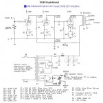
Short across the 300B grid resistor R5 (connect the 300B Grid to Ground),
Does the hum go away?
Please check that, report back the answer, and remove the shorting wire across R5.
Is the RCA phono input jack insulated from the chassis?
Use insulating washers on that jack.
Then connect the input circuit grounds as follows (create a Local Ground Loop, not a long ground loop).
RCA jack return connection to the bottom of the 100k Ohm input potentiometer,
and to the bottom of the input triode's RC self bias resistor and bypass cap, R1 C1.
After that, connect another wire from the bottom of R1 C1 to your center ground.
Connect the center ground point to the chassis.
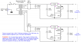
Are you connecting the B+ center tap Directly to C6, and using a second wire from C6 to C7,
and after that, Then connecting another wire from C7 to your central ground point?
If not, you have created a 100Hz ground loop that is getting into sensitive circuits, like your 6SN7 stages.
You are hearing 100Hz hum, right?
That is 2X 50Hz power mains frequency.
Chokes radiate magnetic fields at 2X the power mains frequency.
Is your choke far away from the output transformer, and are they oriented at right angles?
Are you using a 3 wire power mains, and 3 wire power cord. If you are, are you connecting the 3 wire ground to your chassis?
Are you using an aluminum chassis? . . . Good!
Are you using a magnetic steel chassis? . . . Bad!
They couple magnetic fields.
Does the hum go away?
Please check that, report back the answer, and remove the shorting wire across R5.
Is the RCA phono input jack insulated from the chassis?
Use insulating washers on that jack.
Then connect the input circuit grounds as follows (create a Local Ground Loop, not a long ground loop).
RCA jack return connection to the bottom of the 100k Ohm input potentiometer,
and to the bottom of the input triode's RC self bias resistor and bypass cap, R1 C1.
After that, connect another wire from the bottom of R1 C1 to your center ground.
Connect the center ground point to the chassis.
Are you connecting the B+ center tap Directly to C6, and using a second wire from C6 to C7,
and after that, Then connecting another wire from C7 to your central ground point?
If not, you have created a 100Hz ground loop that is getting into sensitive circuits, like your 6SN7 stages.
You are hearing 100Hz hum, right?
That is 2X 50Hz power mains frequency.
Chokes radiate magnetic fields at 2X the power mains frequency.
Is your choke far away from the output transformer, and are they oriented at right angles?
Are you using a 3 wire power mains, and 3 wire power cord. If you are, are you connecting the 3 wire ground to your chassis?
Are you using an aluminum chassis? . . . Good!
Are you using a magnetic steel chassis? . . . Bad!
They couple magnetic fields.
Last edited:
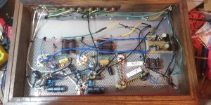
why not post more clear photos of the wiring inside the tube amp to attract more attention.
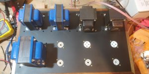
Sure. Here are some. The blue things are chokes and the black ones are OPTs.
Attachments
First your device needs an input RC filter and maybe an input coupling cap (if the source carries a DC offset voltage). The established design also lacks established grid stopper resistors.... I take chassis to be connected to PE only ?! Please note that safety is non debatable so chassis has to be connected to PE and that RF is available in any home for free so precautions against RF are a must.
You could solder the RCA GND lugs together, cutoff the GND of both input cables at the tube end and then solder a single GND wire to the RCA lugs from the GND point. You may also try out a 10 Ohm resistor (with switch in parallel to short it) to check if you have a ground loop.
* just a tip: when pulling cables or wires through holes in metal chassis rubber grommets should be used to avoid wire shaving/damaging the insulation. Also connections of wires to other wires should be insulated to prevent short circuits against chassis and for normal safety.
Last edited:
some wires are twisted beautifully but some are not
some wires are hanging in the air,
will you use sleeved single core wire so you can mount them stick to the metal chassis.
or rewire them in a reasonable format and use glue to stick them to the metal case.
just to minimize the noise.
you are very thoughtful to use a metal net to hold the components,
is the net mechanically stick to the chassis and can be a good grounding.
Last edited:
here's a link may be of a little help for the wiring, DC heating is used.
300B Single-Ended (SE) Tube Amplifier Schematic (6SN7 input)
above link and more wirings are taken from:
300b wiring photos - Google Search
its very convenient to take them for ref. to upgrade the wiring.
300B Single-Ended (SE) Tube Amplifier Schematic (6SN7 input)
above link and more wirings are taken from:
300b wiring photos - Google Search
its very convenient to take them for ref. to upgrade the wiring.
Sorry, maybe you have stated this in your posts earlier, but what AC are you getting on your filament regs? It’s strange to see that your hum increases when you drop a channel. I think that and 100hz are key.
FYI I am tracking down 100 hz in my mc phono stage, it’s not huge, but I would like to get it lower.
I hope you get it sorted, and are able to shed some light on the issue.
FYI I am tracking down 100 hz in my mc phono stage, it’s not huge, but I would like to get it lower.
I hope you get it sorted, and are able to shed some light on the issue.
What is the solid green wire running from what appears to be the AC mains input to the signal input jacks?
A good find. It seems it is connected from PE to the GND of input RCA connectors or the back cover.
Last edited:
Thanks everyone for your input. Here are some answers to the posts that need them.
- I hadn't twigged to the lack of grid stopper resistors. I'll add them in, but the lack of them seems unlikely to account for 100Hz hum (as opposed to oscillation). Is that right?
- The chassis is connected to safety earth (3 pin plug). The safety earth is connected to circuit ground by an 8 ohm power resistor bridged with a small capacitor.
- The solid green wire is safety earth from the aluminium panel that the input and output jacks are mounted to. It only connects to safety ground.
- AC ripple on the 5V filament supply is 6mV.
As jean-paul has said, first apply due diligence. Grid stops, RFI filtering, output Zobels, etc. don't appear on these schematics from 1990s Japanese magazines, but they do matter.
Also, 6A3Summer's diagnostic step is important - if this is a simpler matter of noise in the input stage (you should hope to be so lucky) you want to rule it completely out, and just removing the 6SN7 isn't completely the same (power supply noise is still there).
But odds are on a ground path issue. Always is. The part that nobody can see in the photos is the important part. We can't see it because the photographer doesn't consider it important. The photographer hasn't drawn a real schematic that imagines the signal and power supply current flows, and believes in his/her schematic "grounds".
There is no such critter as a "ground". Never has been, never will be.
All good fortune,
Chris
Sorry if I am focusing on the heater supply, I suggest you keep following other posters instructions. I looked at the data of your rectifiers, and it says 1v drop per diode! I wonder if that means 2 volts. What is the input voltage to the regs I wonder? I have a phono stage that had hum because the dc heater supply reg was starved, and had ripple, once I solved that problem, ripple and hum went away.
This conversation is getting me to rethink how I did my grounds in my other pre. It’s a variant on Allen wrights SVP. The gain at 50 to 100 hz is mind blowing, and sorting hum is tough.
This conversation is getting me to rethink how I did my grounds in my other pre. It’s a variant on Allen wrights SVP. The gain at 50 to 100 hz is mind blowing, and sorting hum is tough.
I’ve just been and tried shorting the grid of the power tube to ground, and it only made a very small difference. Tomorrow night I’ll try updating the grounding as per the suggestions above, including linking the input jack ground tabs. Will also try the battery on the filaments and md see if that helps.
With regards to adding grid stoppers, how important are the values? Should there be one for each stage, ie each half of the 6SN7 and the 300B?
With regards to adding grid stoppers, how important are the values? Should there be one for each stage, ie each half of the 6SN7 and the 300B?
Last edited:
Cool. So now you know that the problem area is the output stage, and therefor comes from either the B+ supply or the filament supply.
handwound's insight that the filament supply regulator might be dropping out seems to fit well with your symptoms, and the inability to null it out with a trimpot (only works for symmetrical noise). You'll know soon, so all good fortune.
Chris
handwound's insight that the filament supply regulator might be dropping out seems to fit well with your symptoms, and the inability to null it out with a trimpot (only works for symmetrical noise). You'll know soon, so all good fortune.
Chris
Last edited:
- Home
- Amplifiers
- Tubes / Valves
- The Odyssey of the Hum Hunter: part 52