With this circuit, Junior phono I got the following resuslts:
12BZ7
G= 49,6 dB,s/n = -73,2 dB weighted A
12AX7
G = 48 dB , s/n = 74 dB
5965
G=41 db s/n = 78 dB
7062
G= 42,6 s/n= 80 dB
ECC81
G= 41,3 s/n = 73 dB
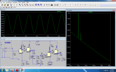
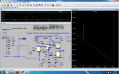
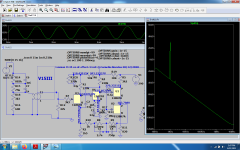
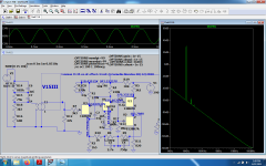
In attach the diagram, I use always this condfiguration where the RIAA network is at low Z
And it is possible to change the tubes ( with a matrix for filaments) and the gain ( with jumper.
In my opinion very good results.
Walter
Walter
ThanksThe parallel on this point is to make easy to get the 7k5 ohm (7k49ohm on E 96) using two 15k. It is only a name
On arti le ( in italian ) is described
Walter
I can't find it...i only see some pcb's for sale .To Dreamth
There is a old thread about Junior with All measurements
The project was presented, tested and listened on Audioreview magazine in Italy
in addition there is a my LCR phono thread on analog section
Walter
Relative to what level? What source impedance?With this circuit, Junior phono I got the following resuslts:
12BZ7
s/n = -73,2 dB weighted A
LCR
LCR phono stage
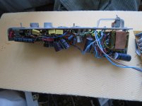
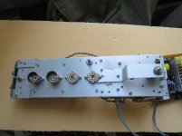
Junior
Junior phono
to MerlinB
as wrote,
5mV in with 600ohm Zsource ( also with 20 ohm, not real difference) fro AP
Weighted "A" , of course
As intl procedure
Walter
LCR phono stage
Junior
Junior phono
to MerlinB
as wrote,
5mV in with 600ohm Zsource ( also with 20 ohm, not real difference) fro AP
Weighted "A" , of course
As intl procedure
Walter
I have got good results with soviet made 6S3P-EV high gm triode. Those tube are still easily available and not expensive. Attached my schematic. Noise level is 6 dB lower than typical 12AX7 design.
Can you give me some DC voltage measurements? Or even just the B+
@waltube
I didn't know your exact values for ecc88 cathode resistors so i just used some typical values(27k and 33k) that keep ecc88 around Vak =90v at good current capabilities and indeed the frequency graph is superb, just the input saturation might not be that great as over 220mv input signal the simulation needs serious convergence rules to even get started and i don't really have the time for this, but 220mv input max signal is most of the time ok and tubes don't behave the same as silicon.Maybe with the right anode and cathode resistors value it will work a little bit better .
On the other hand here's also a modified version of Luxman CL-34 clone, active riaa, with no dc offset supplied only from a 12v dc smps that's already simulated, built and listen to and its input saturation goes up to insane values like 12 RMS with tube like distortions and clipping occuring at 15v rms as for its distortion behavior...it speaks for itself.12ax7 mullard and 12bh7 CEI tubes were used in the real circuit.I don't want to get you through my d3a hybrid circuit with pasive riaa that could reproduce perfect square waves at 20khz, it's just that i used National Semiconductor(now TI) riaa from that datasheet and also a 3 times lower impedance riaa network than yours in the same circuit and i could measure same square waves at 20 khz on both networks, but the higher impedance network sounded more relaxed and i preffered that to the lower impedance one.I couldn't simulate it at the time to see its harmonic content , i didn't know how to use a simulator back then, nor i had a soundcard at least to measure some harmonics, but i bet it was pretty different.The lower impedance network sounded more analytical, clearer, but i preffered the larger impedance one in the end for its more vibrant and more relaxed sound .
I still have about 10 d3a tubes i bought years ago when 19euros/ piece was somwhat affordable, but i can't find the time to rebuild that circuit.
Attachments
-
 junior.png160.8 KB · Views: 237
 -
 junior2.png151.6 KB · Views: 225
 -
 junior3.png157.9 KB · Views: 224
 -
 luxmancl341.png177.2 KB · Views: 222
 -
 luxmancl342.png174.4 KB · Views: 225
 -
 luxmancl343.png172.6 KB · Views: 55
 -
 luxmancl344.png176.2 KB · Views: 77
 -
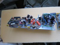 IMG_5995.jpg977.5 KB · Views: 109
 -
 IMG_5998.jpg822.6 KB · Views: 91
 -
 IMG_6000.jpg888.5 KB · Views: 78
Last edited:
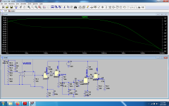
The Rk of both 88 are 12kohm and the current is around 8-9 mA with Vdc of 200 volt (around)
That , in my opinion, is very good.
The 83 works at 1 mA
In a low gain the max input for 1% of THD is 70 mV at 1kHz( = 8,5 volt rms out); the gain is 41,7 dB
This is good for all purposes.
Of course changing the brand the working point moves a bit but it is not a problem
Walter
That , in my opinion, is very good.
The 83 works at 1 mA
In a low gain the max input for 1% of THD is 70 mV at 1kHz( = 8,5 volt rms out); the gain is 41,7 dB
This is good for all purposes.
Of course changing the brand the working point moves a bit but it is not a problem
Walter
I think I already deleted the asc.file with your schematic, but iItried 15kohm and 22kohm while 27 k and 33k performed better allowing 220mv input , while you don't really need the lower noise provided by the usual 8 ma of ecc88.It might help though at driving a littel bit better the riaa network, but i found no evidence for that in the simulator cause higher input also means higher drive for that riaa network .
I decided to set in that way the circuit after some lab test in addition with listening test.
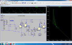
I also tes the 6N6 and 6H30 at 10-12 mA; they are also ok
The reason is also the possibility to change the gain stage and CF using a good range of alternatives
Last, the ss HT stabilized power helps on s/n
note: I have a AP Riaa test ( software compiled) that is the most precise curves possible indipendent form Zsource (I can work with 20,150 and 600 ohm) and this got me a great help on trimming the response
Walter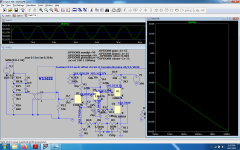
Last edited:
6n6p should theoretically work better on such low loads as it is identical in specifications with e288cc which performs basically as 2x e88c in parallel, but 16ma at 110v AK is a lot of heat to deal with.I tried both e288cc and 6n6p yet e288cc is superior by having both triodes identical in parameters , while 6n6p has a significantly larger spread and you need to use one tube for both channels for each stage to keep the fillament to cathode voltage in sight and that's not really ideal for channel separation with high impedance devices like tubes.
Last edited:
+Ub = 300 V. At plate 160 V, at cathode 2,0 V. That works fine with 250 V as +Ub too. THD is just a bit higher, still very low.
What harm would there be in using 300VDC well filtered but unregulated?
I'm quickly learning about RIAA, or how little I knew about it!
What would prevent using a combination of two 6DJ8's and two solid state cathode followers, where the 6DJ8's provide three lower gain stages (maybe two in tubes parallel on the input) and the Fet's/BJT's are used to drive the RIAA filter and the output?
My thinking (rightly or wrongly) is this will allow a ground reference DC heater supply and possibly better input stage noise and more input headroom.
Sorry I think I was a bit ambiguous - I'm suggesting three 6DJ8 gain stages in two twin triodes, so it goes:
triode//triode ->FET SF ->RIAA filter ->triode ->triode ->FET SF -> output
The gain would be excessive, so could be reduced in the input stage a bit to lower input capacitance.
Then again, using a single 12AX7 and two Source followers might be just as good...?
triode//triode ->FET SF ->RIAA filter ->triode ->triode ->FET SF -> output
The gain would be excessive, so could be reduced in the input stage a bit to lower input capacitance.
Then again, using a single 12AX7 and two Source followers might be just as good...?
Last edited:
That is, the only cases where valve noise is really critical are MC amplifiers without step-up transformer and during the silence between records, when there is no record surface noise.
I'm remined of MarcelvdG's post above that suggests that input tube noise is not that critical in the real world, so maybe just a couple of 12AX7's in two CCDA circuits is the way to go after all..
- Home
- Amplifiers
- Tubes / Valves
- Is it possible? Good RIAA phono amp using new tubes?